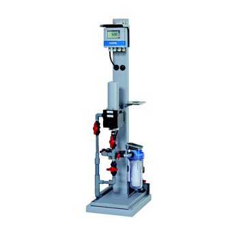
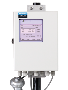
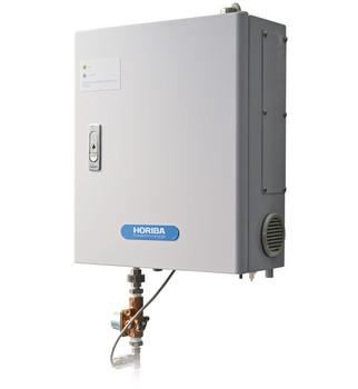
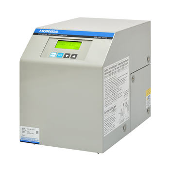
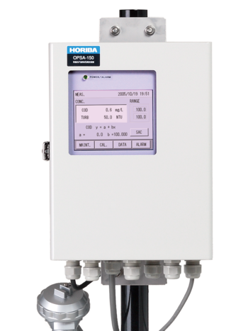
Converter
| Product name | High-sensitivity turbidity meter | |||
|---|---|---|---|---|
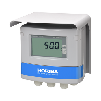
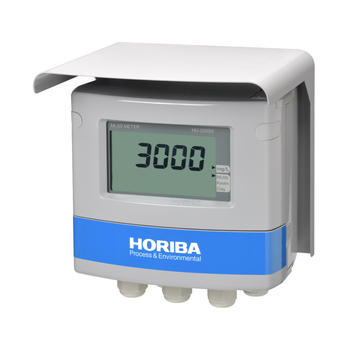
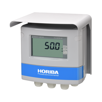
| Model | HU-200TB-H Turbidity converter | |||
| Turbidity sensor type | SS-120-H Turbidity detector | |||
| Measurement range | Kaolin | 0 to 10.00 (degrees) (Display range: 0 to 11.00 (degrees)) | ||
| Formazin (NTU) | 0 to 10.00 (NTU) (Display range: 0 to 11.00 (NTU)) | |||
| PSL | 0 to 10.00 (degrees) (Display range: 0 to 11.00 (degrees)) | |||
| Transmission output setting range | Kaolin | Arbitrary setting within the range from 0 to 0.1 (degrees) to 0 to 11 (degrees) | ||
| Formazin (NTU) | ||||
| PSL | ||||
| Display resolution |
| |||
| Performance | Repeatability | Within ±2% of the reading or ±0.04 degrees, whichever is larger (checked using the span bottle) | ||
| Linearity | The deviation at the mid-range point of the span calibration value is within ±2% of the span calibration value or ±0.04 degrees, whichever is larger | |||
| Transmission output | Number of current outputs | 2 | ||
| Output type | 4 mA to 20 mA DC, input/output isolation type | |||
| Load resistance | 900 Ω(max.) | |||
| Linearity | Within ±0.08 mA (limited to the current linearity) | |||
| Repeatability | Within ±0.02 mA (limited to the current repeatability) | |||
| Error output | Provided with burnout function (3.8 mA or 21 mA) | |||
| Hold function | Selectable between the latest value hold and the preset value hold | |||
| Contact output | Number of output points | 6 | ||
| Output type | No-voltage output contact | |||
| R1, R2 | Contact type | Relay contact, SPST (1a) | ||
| Contact capacity | 250 V AC 3 A, 30 V DC 3 A (resistance load) | |||
| Contact function | Selectable from among the upper limit alarm, lower limit alarm,during transmission output hold, and cleaning output (closed at alarm operation, open under normal conditions and in a power-OFF state) | |||
| Description of alarm |
| |||
| R3 | Contact type | Relay contact, SPST (1a) | ||
| Contact capacity | 30 V DC 1 A (resistance load) | |||
| Contact function | Selectable from among the upper limit alarm, lower limit alarm, during transmission output hold, and cleaning output (closed at alarm operation, open under normal conditions and in a power-OFF state) | |||
| Description of alarm |
| |||
| FAIL | Contact type | Relay contact, SPDT (1c) | ||
| Contact capacity | 250 V AC 3 A, 30 V DC 3 A (resistance load) | |||
| Contact function | Error alarm (closed under normal condition, open in an error or power-OFF state) | |||
| Description of alarm |
| |||
| RANG1, RANG2 | Contact type | Relay contact, SPST (1a) | ||
| Contact capacity | 30 V DC 1 A (resistance load) | |||
| Contact function | Status output of the transmission output range | |||
| Control output for automatic zero calibration (SAMPLE OUT, ZERO OUT) | Number of output points | 2 | ||
| Output type | Voltage contact output (connection power supply voltage output) | |||
| Contact capacity | 250 V AC 0.5 A | |||
| Contact function | SAMPLE OUT: Electric ball valve control output ZERO OUT: Solenoid valve control output | |||
| Contact input | Number of input points | 4 | ||
| Contact type | Open collector no-voltage “a” contact | |||
| Condition |
| |||
| Contact function | EXT1 | Switchable between cleaning command and transmission hold | ||
| EXT2 | Switchable between automatic zero calibration command and transmission hold | |||
| EXT3, EXT4 | Selection command from four ranges using 2-bit contacts | |||
| Communication function | Type | RS-485 | ||
| Signal form | Two wire type, the power source of the communication is isolated from the power of measurement circuit. (The power source of transmission and communication are not isolated.) | |||
| Calibration | Calibration method | Zero calibration | By filtered clean water | |
| Automatic zero calibration | Zero calibration is performed automatically by switching to the filtered clean water (option) | |||
| Span calibration | Turbidity adjustment method by coefficient input | |||
| Compatible standard substances | Kaolin, Formazin, PSL | |||
| Automatic zero calibration (option) | Zero calibration method | The electric valve of a sample line is closed, the electromagnetic valve of a zero line is opened, measured value is automatically judged to be zero within a time, and zero calibration is carried out. | ||
| Setting | Calibration cycle | 1 to 999 (h) | ||
| Stability time | 1 to 60 (s) | |||
| Stability level | 0.001 to 0.005 (degrees/NTU) | |||
| Hold time | 60 to 600 (s) | |||
| Cleaning function (option) | Cleaning method | Electric wiper type (executes cleaning operation by communicating with the converter) | ||
| Setting | Cleaning cycle | 0.1 to 168.0 (h) | ||
| Cleaning time | 20 to 600 (s) | |||
| Hold time | 60 to 600 (s) | |||
| Timer accuracy | Difference within 2 min per month | |||
| Self-check | Converter error | CPU abnormality, ADC abnormality, memory abnormality | ||
| Operating temperature range | −20℃ to 55℃ (no freezing) | |||
| Operating humidity range | Relative humidity: 5 to 90 (%) (no condensation) | |||
| Storage temperature | −25℃ to 65℃ | |||
| Power supply | Rated power supply voltage | 100 V to 240 V AC ±10% 50/60 Hz | ||
| Power consumption | 35 VA (max.) when an automatic cleaner is connected. | |||
| Others | With built-in power switch for maintenance | |||
| Compatible standards | CE marking | EMC :EN61326-1* Class A, Industrial electromagnetic environment Safety :EN61010-1 RoHS :EN50581 9. Industrial monitoring and control instruments | ||
| FCC rules | Part 15 Class A | |||
| Structure | Installation | Outdoor installation type | ||
| Installation method | 50 A pole-mounted or wall-mounted | |||
| Protection class | IP65 | |||
| Material of case | Aluminum alloy (coated with epoxy-modified melamine resin) | |||
| Material of mounting brackets | SUS304 | |||
| Material of hood | SUS304 (coated with epoxy-modified melamine resin) | |||
| Material of display window | Polycarbonate | |||
| Display element | Reflective monochrome LCD | |||
| External dimensions | 180 (W) × 155 (H) × 115 (D) mm (excluding brackets) | |||
| Mass | Mainframe: approx. 3.5 kg (excluding brackets), hood, bracket: approx. 1 kg | |||
*: The surge test specified in the EMC Directive for CE Marking shall not apply to the case when a sensor cable, transmission cable, or contact input cable is extended for 30 m or longer.
Note
Although an arrestor (400 V discharge starting voltage) is mounted for the output signal, contact input, and communication, install an optimum surge absorber element on the connection line, depending on the surrounding environment, device installation conditions, and external connection devices.
Detector
| Product name | Turbidity detector |
|---|---|
| Model | SS-120-H |
| Measurement principle | 90-degree transmission-scattering method |
| Light source | Red LED, 660 nm |
| Detector | Silicon photo diode |
| Detection window | Inside diameter: φ30 mm, hard glass tube |
| Data transfer | RS-485 (communication with converter) |
| Sample water temperature | 0℃ to 45℃ (no freezing) |
| Sample water pressure | 0 to 0.3 (MPa) |
| Material of liquid contact section | PVC, SUS316, FKM, silicon, hard glass, EPDM |
| Cable length | Standard accessory cable: 5 m |
| Installation | Screwing bore size: Rc3/4 |
| Power supply | 12 V DC supplied from HU-200TB-H converter |
| External dimensions | 131 (W) × 450 (H) × 224 (D) mm |
| Mass | Approx. 3.5 kg (excluding cable) |
