Thermal Power Generation
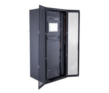
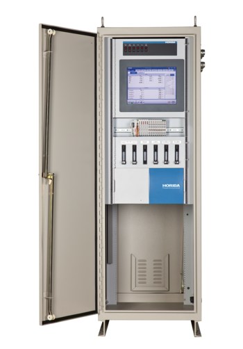
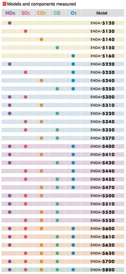
Model | ENDA-5000 | ||||||
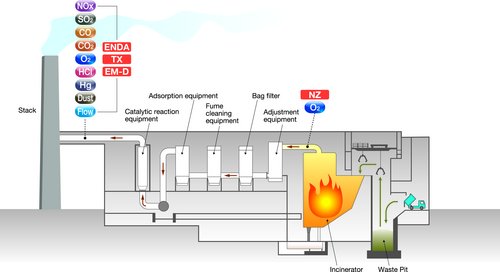
Component*1 | NOx | SO2 | CO | CO2 | O2*2 | ||
Measurement methods | NDIR | NDIR | NDIR | NDIR | Magneto-pneumatic detection | ||
Range*3 | Standard | 200~5000 ppm | 200~5000 ppm | 200~5000 ppm | 5~25 vol% | 10~25 vol% | |
| Option | 100 ppm~ | 50 ppm~ | 100 ppm~ | - | - | |
Range Ratio | Within a factor of 10 | Within a factor of 10 | Within a factor of 10 | Within a factor of 5 | Within a factor of 2.5 | ||
Repeatability | Within 0.5% of full scale/week (with optional range, or during O2 measurement, ±1.0% of full scale/week) | ||||||
Linearity (indicator error) | ±1.0% of full scale | ||||||
Zero drift | ±1.0% of full scale/week (assuming surrounding temperature is maintained within 5 °C) | ||||||
Span drift | ±2.0% of full scale/week (assuming surrounding temperature is maintained within 5°) | ||||||
Response time (Td+T90)*4 | < 50 s from the analyzer inlet | ||||||
Overall interference from co-existing gases | ±2.0% of full scale (within standard range, with standard gas formation) | ||||||
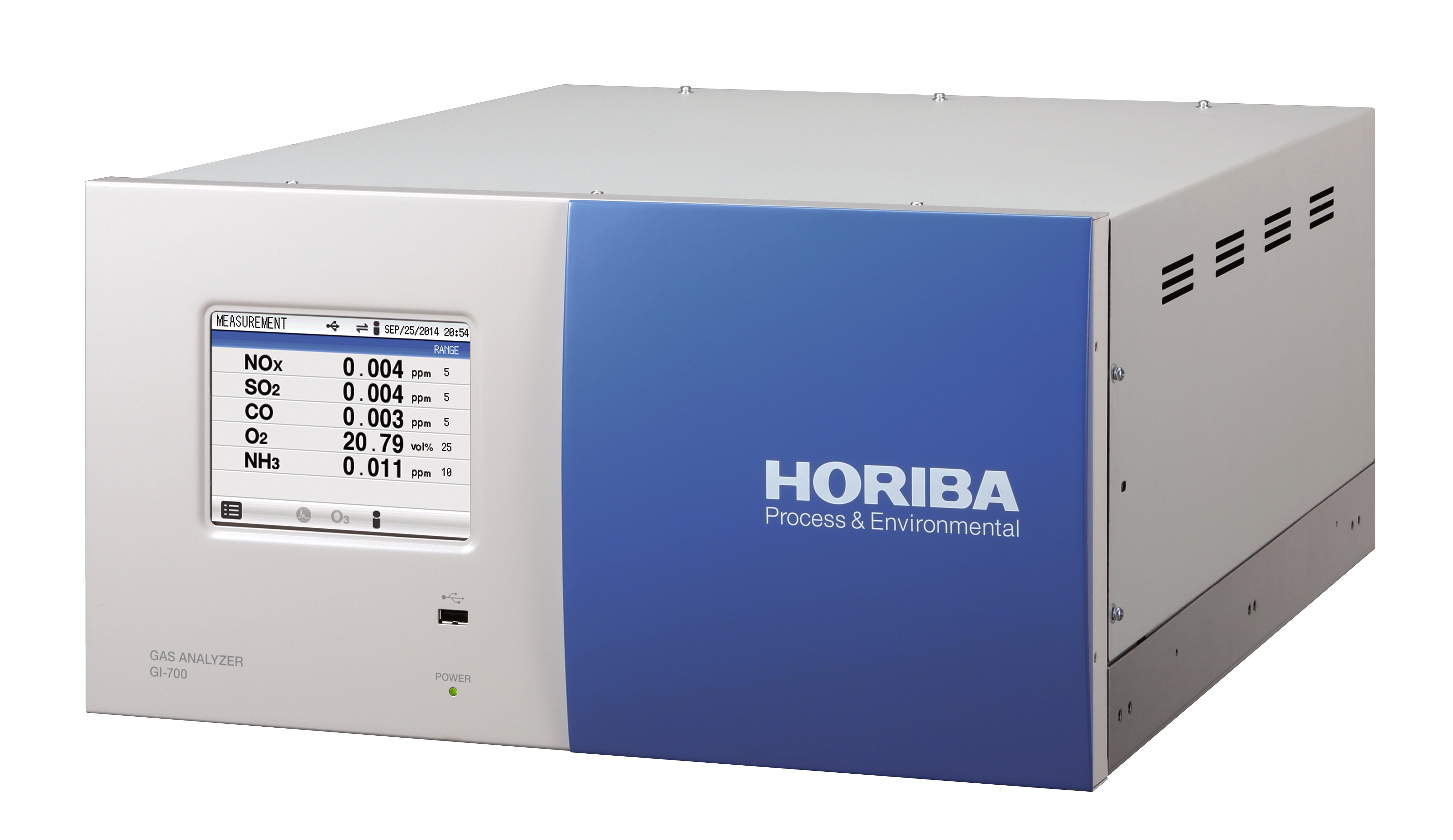
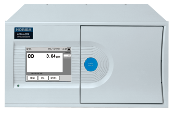
Display | Touch panel LCD (backlight) (four usable lines) | ||||||
Environment | Temperature | -5 to 40 °C (away from direct sunlight and radiation heat )*5 | |||||
Humidity | 85% or less (no condensation) | ||||||
Vibration | 100 Hz, 0.3 m/s2or less | ||||||
Dust | Standard environment or better | ||||||
Measuring Gas Condition | Temperature | 250 °C or lower | |||||
Dust | 0.1 g/Nm3 or less | ||||||
Standard gas composition*6 | NO: 500 ppm or less; NO2: 15 ppm or less; SO2: 1000 ppm or less; SO3: 50 ppm or less; | ||||||
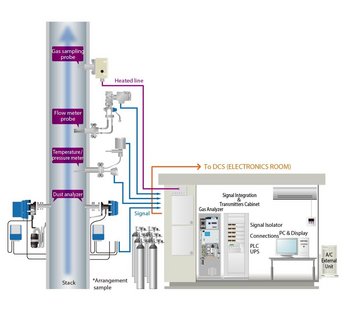
Sampling method | Dry sampling using an electric cooler | ||||||
Sample gas flow | 2.5 L/min~3.0 L/min | ||||||
Sample inlet tube | Teflon tubing (Ø8/Ø6 mm) | ||||||
Sample gas pressure | ±4.9 kPa (three points selected) |
| |||||
Pressure control | Pressure control uses a regulator and pump; Reduced pressure sampling; Control pressure: -4.9 kPa | ||||||
Output | DC 4 to 20 mA (absolute output) (DC 0 to 16 mA/DC 0 to 1 V/DC 1 to 5V optional) Max. 12 output systems | ||||||
External output | Analysis alerts, analysis warnings, range display, corrections, conservation, purging (option) | ||||||
Correction method | Dry correction, automatic correction (correction cycle: 7 days standard, can be adjusted to between 1 and 99 days), manual correction | ||||||
Calibration gas | Zero gas | With measurement method authorization: N2, When there is no measurement method authorization: N2 or ambient air | |||||
O2 carrier gas | Ambient air | ||||||
Span gas | Gas cylinder for each component measured (when there is no measurement method authorization: O2 or ambient air can be used) | ||||||
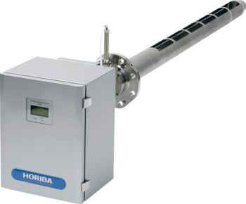
Probe collection point filter | Flange: JIS 10K, 40 AFF; Sample probe tube length: 1000 mm; Material: SUS-316 stainless steel; | ||||||
Power supply | AC 100 V ±15 V(85 V~115 V), AC 230V ±15 % | ||||||
Power frequency | 50/60 Hz (switchable) | ||||||
Power consumption | About 800 VA (heated piping 30m: +1100 VA; heater in tray: +300 VA) | ||||||
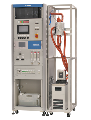
Exterior dimensions/Mass | 600 (W) x 1770 (H) x 300 (D) mm, Approx. 200kg | ||||||
Materials in contract with sample gas | SUS-316 stainless steel, SUS-304 stainless steel, Teflon, polypropylene, polyethylene, | ||||||
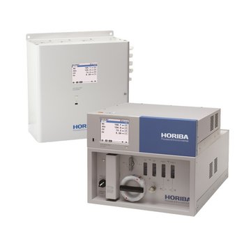
Enclosure | Independent outdoor installation | ||||||
Color/Finish | Semi-gloss Munsell 5Y7/1 on all inner and outer surfaces | ||||||
*1: CH4 and N2O measurement are also available. Please contact us for more information.
*2: No carrier gas cylinder is required.
*3: Up to two ranges are supported for each component.
*4: If response time from sample intake at the stack is required, please feel free to consult us.
*5: Support is available for -15 to 40 °C (cold-climate version) and 5 to 50 °C.
*6: An NH3 scrubber is available as an option for cases where a combined gas includes NH3. SO2 measurement corrected for CH4 interference is available for cases where there is CH4 in the sample gas for SO2 measurement. CO measurement corrected for N2O interference is available for cases where there is N2O in the sample gas for CO measurement.