PDF
12.44
MB

HORIBA Scientific General Product Catalogue 2022
Browse our Product Catalogue and pick the solution that best fits your application needs.

HORIBA provides advanced analytical instruments, supporting research, education, and industry with precision tools. As an OEM partner, HORIBA delivers customizable spectroscopy and imaging solutions -monochromators, detectors, gratings, and cameras- engineered for seamless integration, high performance, and reliability. From laboratories to OEMs, HORIBA drives innovation across scientific applications.
Featured product
LabRAM Soleil
Raman Spectroscope - Automated Imaging Microscope
Push the limits of Raman analysis with LabRAM Soleil, delivering high-speed imaging, exceptional sensitivity, and nanoscale resolution.
Product information 〉
Brochure 〉
Contact us 〉
Contributions to Efficient Research and Development and Quality Control of Advanced Materials
HORIBA has developed the PoliSpectra® 27, a compact, lightweight industrial spectrometer platform designed to support high-volume manufacturing and…
HORIBA is proud to announce that the Veloci™ BioPharma Analyzer has been selected by The Analytical Scientist as one of its Top 10 Most Innovative…
HORIBA is proud to announce the release of the RZ-660 In Vivo Raman Analyzer, a benchtop instrument designed for real-time, non-invasive molecular…
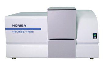
Aqualog®-Next is a dual-function spectrometer that simultaneously acquires absorbance and fluorescence excitation-emission matrices (EEMs) using…
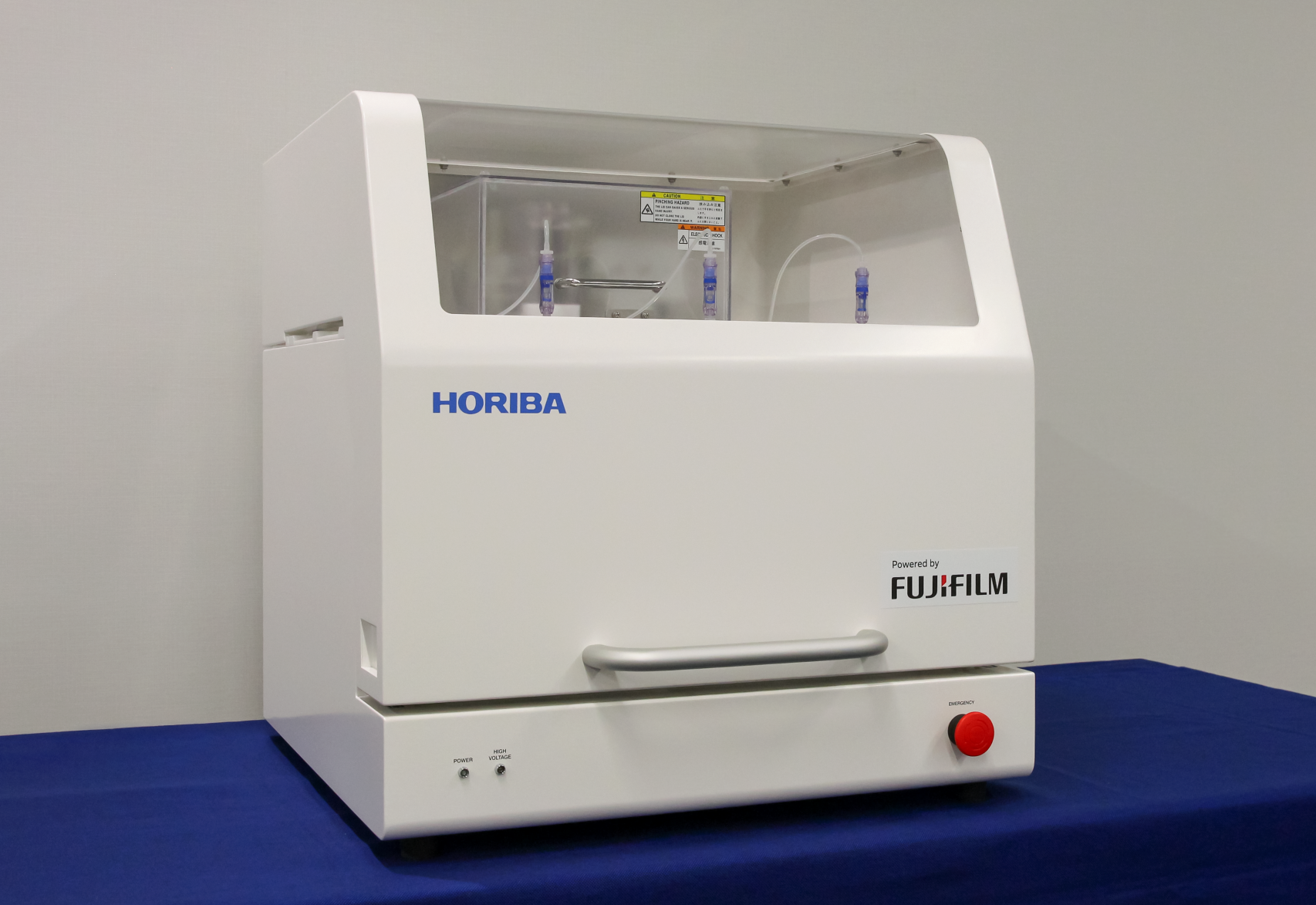
Aiming to Commercialize Industry-first Continuous Electroporation Technology
The use of imaging techniques is of fundamental importance in uncovering the structure and dynamics of both biological substances and…
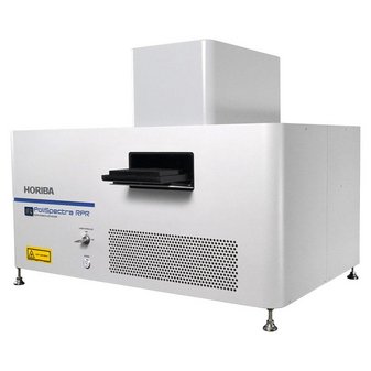
HORIBA proudly announces the launch of the PoliSpectra® Rapid Raman Plate Reader (RPR) for Raman High-Throughput Screening (HTS).
HORIBA is proud to announce an expanded portfolio of instruments tailored to meet the rigorous demands of the pharmaceutical industry.
Do you have any questions or requests? Use this form to contact our specialists.