
A mass flow controller automatically controls the flow rate of a gas according to a set flow rate sent as an electric signal, without being affected by use conditions or changes in gas pressure. Flow rates can be roughly classified into two types: volumetric flow and mass flow. A volumetric flow measurement is affected by ambient temperature and pressure. To see the true flow, the pressure and temperature conditions need to be pressure conditions, therfore providing much more accurate and stable flow measurement and control. Our mass flow controllers are used in a wide range of industrial fields as indispensable equipment when accurate control of flow rates is required or an automated production line is built.
These mass flow controllers have a flow rate measurement section that includes a sensor, bypass, flow rate control valve, and special circuitry.
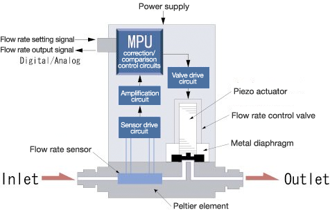
The gas is input from an Inlet joint, and is divided so that it flows over both the flow rate sensor and a bypass. The sensor measures the mass flow rate of the gas, and the flow rate control valve modifies the flow rate so that the difference between the measured flow rate and the flow rate received from the external flow rate setting signal is 0 (zero).
The units feature a loop circuit, so even if there is a secondary pressure change or ambient temperature change that could affect the supply pressure of the introduced gas, the flow rate is instantaneously corrected, which ensures stable flow rate control.
The Digital Mass Flow Controller is shown in the diagram above.
These mass flow controllers have a flow rate measurement section that includes a sensor, bypass, flow rate control valve, and special circuitry. A CPU is part of the circuitry, which makes it both multi-functional and highly efficient.
The units feature a loop circuit, so even if there is a secondary pressure change or ambient temperature change that could affect the supply pressure of the introduced gas, the flow rate is instantaneously corrected, which ensures stable flow rate control.
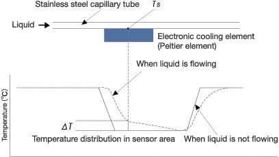
The flow rate sensor in the LF-F/LV-F series of fine mass flow controllers for liquids consists of an electronic cooling element (Peltier element) that is in contact with a capillary tube, as well as several temperature detection elements. When the liquid is flowing, the sensor detects the temperature rise (⊗T) corresponding to the flow rate and displays it as a flow rate. Unlike methods where heat is added, this cooling method enables flow rate measurement of liquids with low boiling points. It also prevents problems with interference due to the influence of secondary discharge (vaporization) and makes accurate flow rate measurements possible.
The LV-F series of mass flow controllers are similar to the LF-F series of mass flow meters, but also have a piezo actuator valve and an internal comparison control circuit. They compare the flow rate setting signal and the flow rate output signal and automatically control the valve aperture so that the two signals will match. Since they use a feedback control system, there are no flow rate variations as a result of external factors, and, therefore, stable, accurate control is possible. The use of a piezo actuator valve, which is both stable and does not generate heat, as the control valve makes these units ideal for flow control of liquids with low boiling points.
The following list covers the major steps involved in vaporizing a liquid source and supplying it to the process chamber.
Vaporization systems that use the injection method sequentially carry out steps 1, 2, and 3 listed above. The VC series units measure the liquid flow of the liquid source using a mass flow meter and do not use a carrier gas. The MI/MV series units use a mass flow meter for measurement and feature a mass flow controller that introduces a carrier gas into the unit to vaporize the liquid source.
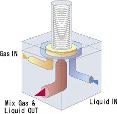
This is the vaporization method used in the MI/MV series. Since the pressure on the carrier gas is higher at the front of the nozzle inside the injector, it can be heated efficiently. The liquid source and the heated carrier gas are mixed together in the gas/liquid mixing area in the front of the nozzle, and the pressure is reduced as they pass through the nozzle, vaporizing the mixture. Vaporization efficiency is higher than with traditional vaporization methods. When this method is used, larger flows can be generated, and the generation temperature can be reduced.
Do you have any questions or requests? Use this form to contact our specialists.