PDF
0.28
MB

Galvanic vs Optical Dissolved Oxygen Sensors

Modern method of dissolved oxygen (DO) measurement in the lab or field involves a DO sensor connected to a meter that records calibration and measurement data. DO sensors can be designed for discrete sampling, biological oxygen demand (BOD) tests, or long-term monitoring applications while DO meters can be equipped with internal barometer, compensation algorithms and other special functions, and be linked to a computer for data transfer.
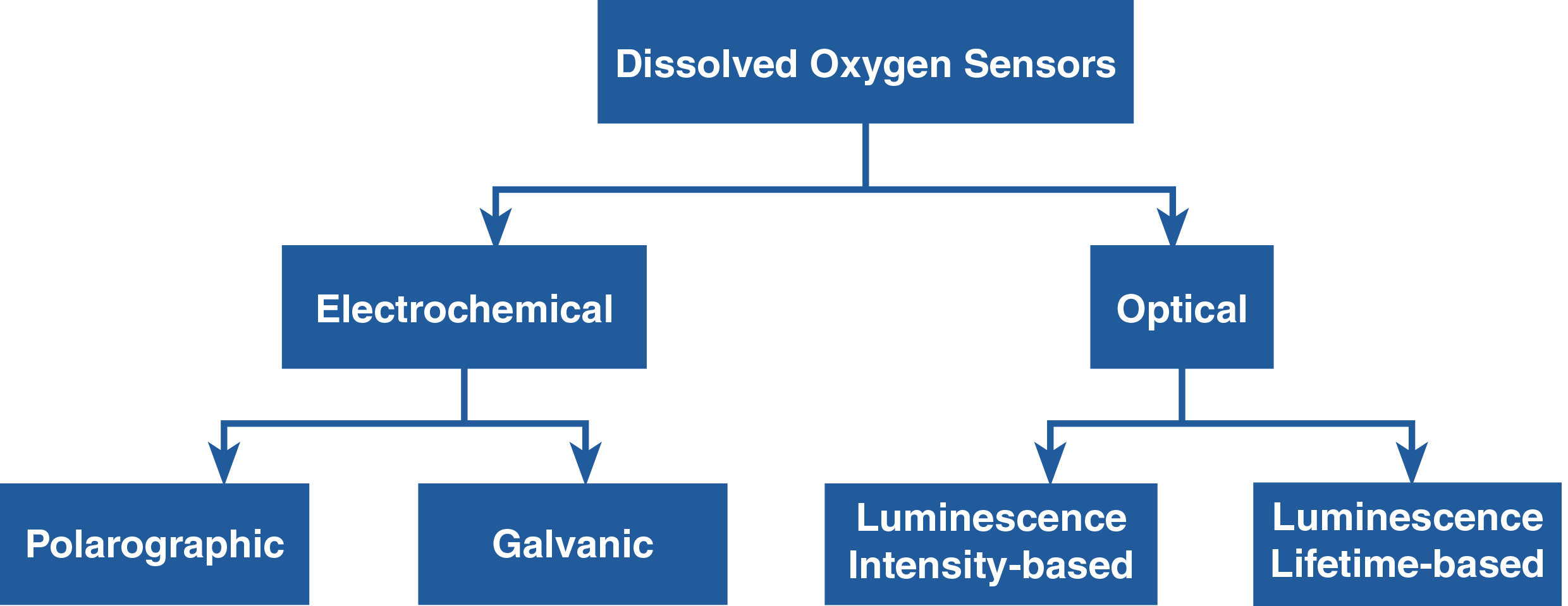
There are two types of DO sensors—electrochemical and optical. Electrochemical DO sensors, also known as amperometric or Clark-type sensors, measure dissolved oxygen concentration in water based on electrical current produced. Polarographic and galvanic are types of electrochemical DO sensors. The advantages of galvanic sensors over polarographic sensors are that they don’t require outside voltage source and warm-up time to operate and their electrolyte can be used for a long time. Optical DO sensors, popularly known as luminescent DO sensors (LDO) but some are called fluorescent sensors, measure dissolved oxygen concentration in water based on the quenching of luminescence in the presence of oxygen. They can measure either the intensity or the lifetime of the luminescence as oxygen affects both.1 The advantages of luminescence lifetime-based sensors over luminescence intensity-based sensors are that they are less susceptible to light source and detector drift, changes in optical path, and drift due to dye degradation or leaching.2 They exhibit long-term stability2 and maintain their accuracy even with some photodegradation.1
HORIBA offers galvanic electrochemical DO sensors and luminescence lifetime-based optical DO sensors. Both sensors are maintenance-free and designed with plug-and-play configuration that consists of two parts—robust sensor body with built-in thermistor and different cable lengths and replaceable DO sensor tip/cap—providing easy, quick, and accurate dissolved oxygen and temperature measurements. To learn more about these DO sensors, please read on.
Galvanic DO Sensor |
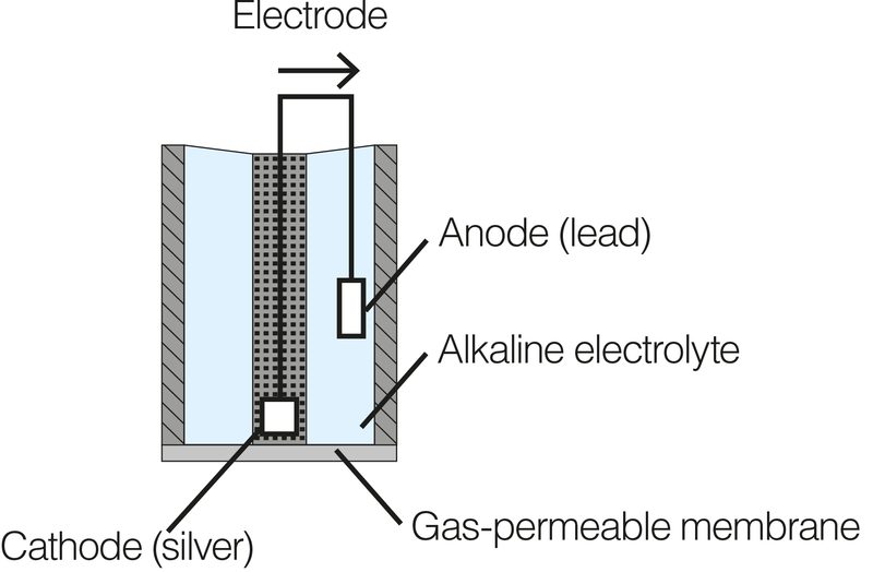
Components:
The cathode and anode are dissimilar metals (different electropotentials). In order to reduce oxygen without an external applied potential, the difference in potential between the anode and the cathode should be at least 0.5V. When placed in an electrolyte solution, the potential between dissimilar metals causes them to self-polarize with the electrons travelling internally from the anode to the cathode. For this reason, galvanic DO sensor does not require any warm-up time.
The cathode (e.g., Ag or another noble metal) accepts electrons from the anode via an internal circuit and passes them on to the oxygen molecules. It does not interfere in the reaction. Thus, the anode (e.g., Zn, Pb, or another active metal) is oxidized and oxygen is reduced at the surface of the cathode. Both the cathode and anode are submerged in an electrolyte (e.g., NaOH, NaCl, or another inert electrolyte) and enclosed in a cap fitted with thin hydrophobic, oxygen-permeable membrane. |
Optical DO Sensor |
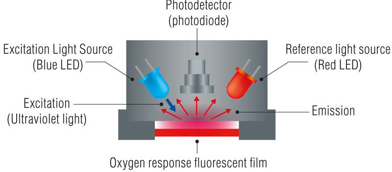
Components:
Dual LED referencing system – blue LED emits light that excites the dye causing its luminescence. The red LED emits light but simply reflected back by the dye and does not cause luminescence. It serves as a reference to ensure accuracy. |
| Galvanic DO Sensor |
When galvanic DO sensor is immersed in water sample, oxygen that diffuses across the oxygen-permeable membrane at a rate proportional to the pressure of oxygen in the water is reduced and consumed at the cathode. This reaction produces an electrical current that is directly related to the oxygen concentration. This current is carried by the ions in the electrolyte and runs from the cathode to the anode. |
| Optical DO Sensor |
When an optical DO sensor is immersed in water sample, oxygen crosses the membrane and interacts with the dye. This quenches or reduces the intensity and lifetime of the dye’s luminescence, which is measured by the photodetector and used to calculate the DO concentration.
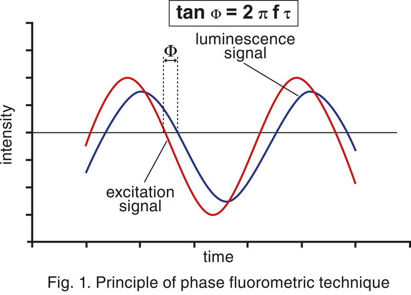
If the excitation signal is sinusoidally modulated, the dye’s luminescence is also modulated but is time delayed or phase shifted relative to the excitation signal. This phase shift is illustrated in Fig. 1. The blue and red LEDs are alternately switched in order to determine the phase difference, ∅ref, due to electronics alone. This phase shift is subtracted in real time from the oxygen-dependent phase shift, ∅sig, to obtain the specific sensor output phase shift.2 |
Galvanic DO Sensor | Optical DO Sensor |
100% DO Calibration | |
Calibration is performed in clean air after allowing the sensor to sit for approximately 20 minutes.
When galvanic DO sensor is connected to any 100 or 200 Series DO meters, the meter will show 105% DO after calibration in percent saturation DO mode. This is equivalent to 100% DO saturation in water. HORIBA determined 5% as the difference between the sensor current in air and in water based on experimental results.
| Calibration is performed in the air calibration bottle that comes with the sensor. The bottle has wet sponge at the bottom to create an environment with water vapor pressure.
When optical DO sensor is connected to any WQ-300 series meters, the meter will show 100% DO after calibration in percent saturation DO mode. |
0% Calibration | |
Calibration is performed in fresh oxygen-free solution which can be prepared by dissolving 2 g of sodium sulfite (Na2SO3), an oxygen scavenger, with 1 L of distilled or deionized water in a container. The membrane and thermistor of the DO sensor should be fully immersed in the solution during calibration. Meter will show 0% DO after calibration in percent saturation DO mode. | |
| Galvanic DO Sensor | Optical DO Sensor |
Stirring | ·Required | ·Not required |
Warm-up time | ·Not required | ·Not required |
Response time | ·Faster than optical DO sensor | ·Fast but takes 2-4x longer than electrochemical DO sensor |
Power consumption | ·Require less power than optical DO sensor | ·Usually require more power than electrochemical DO sensor |
Calibration | ·Retains calibration data in the meter ·Tends to drift away from calibration so frequent calibration is required | ·Retains calibration data in the sensor head ·Hold calibration better with little drift but regular calibration is still recommended |
Membrane | ·Vulnerable to damage and wear and tear | ·Durable |
Lifetime | ·Shorter than optical DO sensor | ·Longer than electrochemical DO sensor |
Replacement Frequency | ·DO tip replacement is every after 6 months depending on the application and handling. ·When the sensor reading is unusually low or unstable or the sensor will not calibrate, the sensor tip needs to be replaced. | ·DO sensor cap replacement is every after 12 months depending on the application and handling. ·The dye degrades over time. When the sensor will not calibrate, the sensor cap needs to be replaced. |
Warranty | ·6 months | ·12 months |
Cost | ·Cheaper than optical DO sensor | ·More expensive than electrochemical DO sensor |
Applications | ·Not suitable for samples containing strong acids and hydrogen sulfide gas | ·Suitable for samples containing strong acids and hydrogen sulfide gas ·More accurate to low DO concentrations ·Require less sample volume |
Type | Galvanic DO Sensor | Optical DO Sensor | ||
Model | 9520-10D (1m cable) | 9551-20D (2m cable) 9551- 100D (10m cable) | 9552-20D (2m cable) 9552-50D (5m cable) | 300-D-2 (2m cable) 300-D-5 (5m cable) |
DO Tip | 7541 | 5401 | 5402 | 300-D-M |
DO Range | 0.00 – 20.00 mg/L | |||
Temperature Range | 0 to 45 °C | 0 to 40 °C | 0 to 50 °C | |
Accessories Included | DO sensor tip, stainless steel DO sensor protective guard | DO sensor cap, air calibration bottle, stainless steel DO sensor protective guard | ||
Application | For laboratory use | For laboratory and field use | ||
Compatible Meters | 100 Series, 200 Series | WQ-300 Series | ||