
Hydraulic fracturing is used in the oil and gas industry to increase the flow of oil and/or gas from a well. The producing formation is fractured open using hydraulic pressure and then proppants (propping agents) are pumped into the oil well with fracturing fluid to hold the fissures open so that the natural gas or crude oil can flow up the well. The proppant size, shape, and mechanical strength influences the integrity of the newly created fractures, and therefore the flow of oil and gas out of the well.
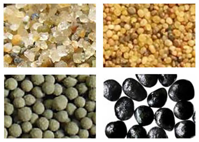
The material used for proppants can range from naturally occurring sand grains called frac sand (top left), resin coated sand (top right), to high-strength ceramic materials (bottom left), and resin coated ceramic materials (bottom right).
The quality control of the proppants is described mainly in ISO 13503-2 (1), which replaces the earlier API standards RP 56, 58 and 60. Among other tests, the standards demand the test of size, shape and crush resistance.
The size range of the proppant is very important. Typical proppant sizes are generally between 8 and 140 mesh (106 µm - 2.36 mm), for example 16-30 mesh (600 µm – 1180 µm), 20-40 mesh (420 µm - 840 µm), 30-50 mesh (300 µm – 600 µm), 40-70 mesh (212 µm - 420 µm) or 70-140 mesh (106 µm - 212 µm). When describing frac sand, the product is frequently referred to as simply the sieve cut, i.e. 20/40 sand.
The shape of the proppant is important because shape and size influence the final permeability through the fracture. A wide range of particle sizes and shapes will lead to a tight packing arrangement, reducing permeability/conductivity. A controlled range of sizes and preferential spherical shape will lead to greater conductivity. The roundness has been historically analyzed (2) using a visual, manual method based on the chart shown in the figure below, originally developed by Krumbein and Sloss. This method results in large subjective differences from operator to operator.
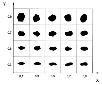
Chart for visual estimation of sphericity (y-axis) and roundness (x-axis)

Laser Scattering Particle Size Distribution Analyzer
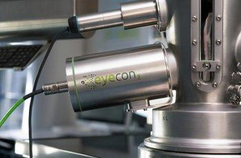
Direct Imaging Particle Analyzer
Do you have any questions or requests? Use this form to contact our specialists.