Size:
5.24
MB
H-1,4896 Details Brochure_English
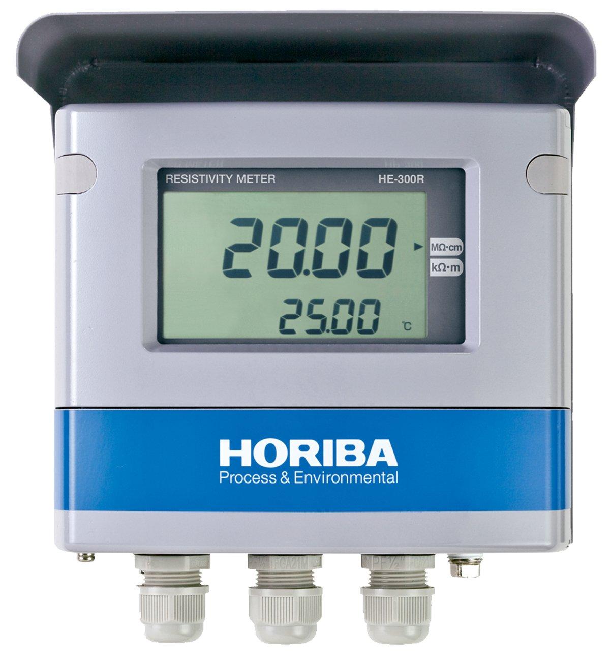
현장 설치형 전기저항계(2-Wire Transmission)
HE-300R은 비저항센서(ERF Series)를 연결하여 시료수의 비저항과 온도를 측정합니다.
UPW 비저항 측정에 적합 합니다.
- 측정 범위(저항) : 0.00 ~ 20.00 MΩ·cm, 0.00 ~ 200.0 kΩ·m
- 온도 : 0.00 ~ 100.00 ℃
| Product name | Resistivity meter | |||
|---|---|---|---|---|
| Model | HE-300R | |||
| Sensors in combination | 2-electrode method resistivity sensor (ERF-001 Series) of cell constant 0.01/cm | |||
| Measuring range | Resistivity | MΩ•cm | 0.000 to 2.000 | 0.00 to 20.00 (*1) |
| kΩ•cm | 0.00 to 20.00 | 0.0 to 200.0 (*1) | ||
| Temperature | ℃ | 0℃ to 100℃ (Display range: −10℃ to 110℃) | ||
| Display resolution | Resistivity | As shown in the measuring table. | ||
| Temperature | 0.01℃ | |||
| Performance | Resistivity | Repeatability | Within ±0.1% of the full scale (response for equivalent input) | |
| Linearity | Within ±0.5% of the full scale (response for equivalent input) | |||
| Temperature | Repeatability | ±0.1℃ (response for equivalent input) | ||
| Linearity | ±0.5℃ (response for equivalent input) | |||
| Transmission output | Output type | 4 mA to 20 mA DC: input/output isolated type | ||
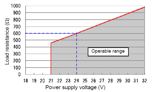
| Load resistance | Maximum: 600Ω Case of 24 V DC power supply | |||
| Linearity | ±0.08 mA (output only) | |||
| Repeatability | ±0.02 mA (output only) | |||
| Output range | Resistivity: Free setting within a measuring range. | |||
| Occasional out for error | Hold or burnout to either 3.8 mA or 21 mA | |||
| Transmission hold | In the maintenance mode, transmission signal is held at the latest value or preset value. In the calibration mode, transmission signal can be alive or held. | |||
| Contact input | Number of input | 1 | ||
| Contact type | No-voltage "a" contact for open collector | |||
| Conditions | ON resistance: 40 Ω max. Open voltage: 1.2 V DC Short-circuit current: 21 mA max. | |||
| Contact function | External input for transmission holding. | |||
| Temperature compensation | Applicable temperature element | Platinum resistor: 1 kΩ (0℃) | ||
| Compensation method |
| |||
| Temperature compensation range | 0℃ to 100℃ (However, the compensation calculation is extended lower than 0℃ or higher than 100℃.) | |||
| Calibration | Resistivity | Based on parameter input of coefficient for the sensor cell constant. | ||
| Temperature | Comparison to the accurate thermometer Both deviation and coefficient of RTD are taken into account for calibration. | |||
| Other function | UPW standard resistivity input | Select one from the next. 182.3 kΩ•m (standard), 181.8 kΩ•m, 182.4 kΩ•m, 18.23 MΩ•cm (standard), 18.18 MΩ•cm, or 18.24 MΩ•cm | ||
| Clipping function | If the measured value exceeds the user setting value for clipping, the measured data will be held at the clipping value. | |||
| Self-check | Electrode diagnostic error | Temperature sensor short-circuit, temperature sensor disconnection, and out of the temperature measurement range | ||
| Meter error | CPU, ADC, and memory errors | |||
| Operating temperature range | −20℃ to 60℃ (without freeze) | |||
| Operating humidity range | Relative humidity: 5% to 90% (without condensation) | |||
| Storage temperature | −25℃ to 65℃ | |||
| Power supply | Rated voltage | 24 V DC (operating voltage range: 21 V to 32 V DC) | ||
| Power consumption | 0.6W max. | |||
| Compatible standards | CE marking | EMC directive: EN61326-1 RoHS Directive: EN50581 | ||
| Immunity Industrial electromagnetic environment | Electostatic discharge | IEC61000-4-2 | ||
| Electromagnetic field of radiated radio frequency | IEC61000-4-3 | |||
| Electric fast transient/burst | IEC61000-4-4 | |||
| Surge | IEC61000-4-5 (*3) | |||
| Conducted interference induced by radio frequency | IEC61000-4-6 | |||
| Emission ClassA | Radiated disturbance | CICPR 11 CLASS A | ||
| Noise terminal voltage | CISPR 11 CLASS A | |||
| FCC Rules | Part15 CLASS A | |||
| Structure | Installation | Outdoor installation type | ||
| Installation method | Mount on 50 A pole or wall | |||
| Protection code | IP65 | |||
| Case material | Aluminum alloy (coated with epoxy-denatured melamine resin) | |||
| Material of fittings | SUS304 | |||
| Material of cover | SUS304 stainless steel (coated with epoxy-denatured melamine resin) | |||
| Material of display window | Polycarbonate | |||
| Display element | Reflective monochrome LCD | |||
| External dimensions | 180 (W) × 155 (H) × 115 (D) mm (excluding mounting brackets) | |||
| Mass | Main body: Approx. 2.8 kg; cover and mounting brackets: Approx. 1 kg | |||
Relation between power supply voltage and load resistance
HORIBA제품의 자세한 정보를 원하시면, 아래의 양식에 내용을 입력을 부탁드립니다.