Size:
5.24
MB
H-1,4896 Details Brochure_English
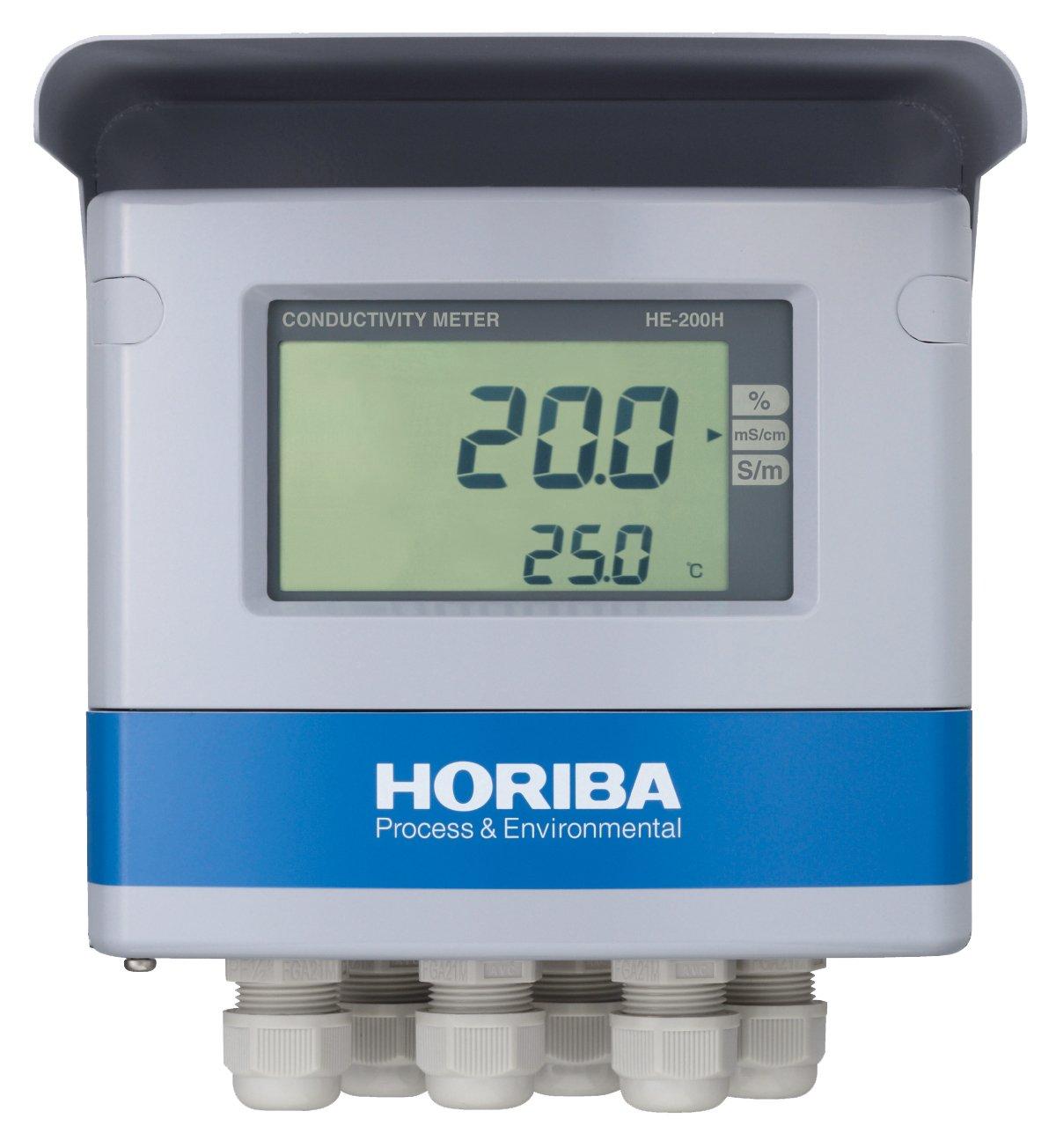
현장설치형 전기전도도계(4-Wire Transmission, 고농도용)
HE-200H는 전도도 센서(FES-125F,126F)를 연결하여 시료수의 전도도 및 온도를 측정합니다.
수용액의 전기전도도 측정은 물론 CIP 등의 농도 조절 및 린스 모니터링, 공정의 농도 모니터링에도 사용할 수 있습니다.
- 측정 범위(전도도) : 0 ~ 2000 mS/cm, 0.0 ~ 200.0 S/m
- 온도: 0.00 ~ 100.00 ℃
| Product name | Conductivity meter | ||||
|---|---|---|---|---|---|
| Model | HE-200H | ||||
| Sensors in combination | 4-electrode method conductivity sensor (FES Series) of cell constant 0.1/cm, or 1.0/cm | ||||
| Measuring range | Measurement type | Unit | Cell constant (/cm) | 0.1 (FES-2XX, 310 series) | 1.0 (FES-125, 126) |
| Conductivity | mS/cm | 0.000 to 2.000 | ○ | ○ | |
| 0.00 to 20.00 | ○ | ○ | |||
| 0.0 to 200.0 | ○ | ○ | |||
| 0 to 2000 | △(*Note2) | △(*Note2) | |||
| Auto (*Note1) | ○ | ○ | |||
| Practical region (*Note2) | 0 to 500 | 0 to 1000 | |||
| Display range | 0 to 2200 | ||||
| S/m | 0.000 to 0.2000 | ○ | ○ | ||
| 0.00 to 2.000 | ○ | ○ | |||
| 0.00 to 20.00 | ○ | ○ | |||
| 0.0 to 200.0 | △(*Note2) | △(*Note2) | |||
| Auto (*Note1) | ○ | ○ | |||
| Practical region (*Note2) | 0.0 to 50.0 | 0.0 to 100.0 | |||
| Display range | 0.0 to 220.0 | ||||
| Temperature | 0℃ to 100℃ (display range: −30℃ to 160℃) | ||||
| Salinity conversion capability | Seawater | 0.00% to 4.00% | |||
| NaCl | 0.0% to 20.0% | ||||
| Concentration conversion capability | NaOH | 0.00% to 5.00% | |||
| HNO3 | 0.00% to 5.00% | ||||
| H3PO4 | 0.00% to 5.00% | ||||
| Option 1 to 4 | 0.00% to 100.00% | ||||
| Display resolution | Conductivity Conversion density | As shown in the measuring and conversion table. | |||
| Temperature | 0.01℃ | ||||
| Performance | Conductivity | Repeatability (mS/cm) | Cell constant | 0.1 (/cm) | 1.0 (/cm) |
| 0.00 to 20.00 | Within ±0.5% of the full scale | Within ±0.5% of the full scale | |||
| 20.0 to 200.0 | Within ±1.0% of the full scale | Within ±0.5% of the full scale | |||
| 200 to 1000 | − | Within ±1.0% of the full scale | |||
| Condition | response for equivalent input | ||||
| Linearity (mS/cm) | Cell constant | 0.1 (/cm) | 1.0 (/cm) | ||
| 0.00 to 20.00 | Within ±0.5% of the full scale | Within ±0.5% of the full scale | |||
| 20.0 to 200.0 | Within ±1.0% of the full scale | Within ±0.5% of the full scale | |||
| 200 to 1000 | − | Within ±1.0% of the full scale | |||
| Condition | response for equivalent input | ||||
| Performance | Temperature | Repeatability | ±0.1℃ (response for equivalent input) | ||
| Linearity | ±0.5℃ (response for equivalent input) | ||||
| Transmission output | Number of output | 2 (The negative terminals for transmission outputs are internally connected at the same electric potential) | |||
| Output type | 4 mA to 20 mA DC: input/output isolated type | ||||
| Load resistance | Maximum: 900Ω | ||||
| Linearity | Within ±0.08 mA (output only) | ||||
| Repeatability | Within ±0.02 mA (output only) | ||||
| Output range | Output 1 | Conductivity or density converted: Free setting within a measuring range. | |||
| Output 2 | Temperature: Free setting within a range between −30℃ and 160℃ | ||||
| Occasional out for error | Hold or burnout to either 3.8 mA or 21 mA | ||||
| Transmission hold | In the maintenance mode, transmission signal is held at the latest value or preset value. In the calibration mode, transmission signal can be alive or held. | ||||
| Contact output | Number of output | 3 | |||
| Output type | No-voltage contact output | ||||
| Contact type | Relay contact; SPDT (1c) | ||||
| Contact capacity | AC 250 V 3 A, DC 30 V 3 A | ||||
| Contact function | R1 and R2 | Selectable from upper limit alarm, lower limit alarm, and currently holding of transmission output. (The contact is closed during alarm operation, opened normally and while the power is down.) | |||
| FAIL | Error alarm (Closed in the normal state, opened in the failure state or while the power is down.) | ||||
| Alarm setting range | Selectable from conductivity and density | ||||
| |||||
| Contact input | Number of input | 2 | |||
| Contact type | No-voltage "a" contact for open collector | ||||
| Conditions | ON resistance: 100Ω max. Open voltage: 24 V DC Short-circuit current: 12 mA DC max. | ||||
| Function of input | The input signal use can be changed. Two inputs for four output current range selection, or, one input for two current range selection and one input for holding. The display also responds for the range selection by input. | ||||
| Communication function | Communication type | RS-485 | |||
| Signal type | 2 wire system, isolated from the input circuit Not isolated from transmission circuit | ||||
| Temperature compensation | Temperature element | Platinum resistor: 1 kΩ (0℃) | |||
| Compensation method |
| ||||
| Temperature compensation range | 0℃ to 100℃ (However, the compensation calculation is extended lower than 0℃ or higher than 100℃.) | ||||
| Calibration | Conductivity | Based on parameter input of coefficient for the sensor cell constant. | |||
| Self-check | Sensor diagnosis error | Temperature sensor short-circuit, temperature sensor disconnection, and out of the temperature measurement range | |||
| Converter | CPU error, ADC error, and memory error | ||||
| Operating temperature range | −20℃ to 55℃ (without freeze) | ||||
| Operating humidity range | Relative humidity: 5℃ to 90℃ (without condensation) | ||||
| Storage temperature | −25℃ to 65℃ | ||||
| Power supply | Rated power supply voltage | 100 V to 240 V AC ±10% 50/60 Hz | |||
| Power consumption | 15 VA (max) | ||||
| Others | With power switch for maintenance use | ||||
| Compatible standards | CE marking | EMC :EN61326-1 Class A, Industrial electromagnetic environment Safety :EN61010-1 RoHS :EN50581 9. Industrial monitoring and control instruments | |||
| FCC rules | Part15 Class A | ||||
| Structure | Installation | Outdoor installation type | |||
| Installation method | Mount on 50 A pole or wall | ||||
| Protection code | IP65 | ||||
| Case material | Aluminum alloy (coated with epoxy-denatured melamine resin) | ||||
| Material of fittings | SUS304 | ||||
| Material of food | SUS304 stainless steel (coated with epoxy-denatured melamine resin) | ||||
| Material of window | Polycarbonate | ||||
| Display element | Reflective monochrome LCD | ||||
| External dimensions | 180 (W) mm x 155 (H) mm x 115 (D) mm (excluding mounting brackets) | ||||
| Mass | Main body: Approx. 3.5 kg; cover and mounting brackets: Approx. 1 kg | ||||
HORIBA제품의 자세한 정보를 원하시면, 아래의 양식에 내용을 입력을 부탁드립니다.