Size:
3.09
MB
SPCS-ONE English Brochure
Solid Particle Counting System
Accurate solid particle number measurement requires controlled sampling, effective volatile-particle removal and reliable detection at increasingly small particle sizes. These capabilities are important for emissions certification and for development programs evaluating engines, vehicles, aftertreatment systems and other particle sources.
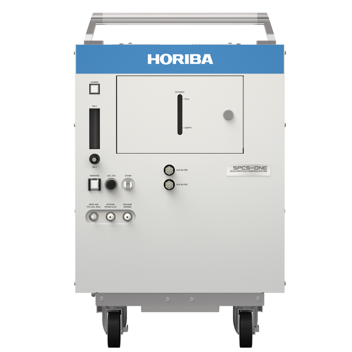
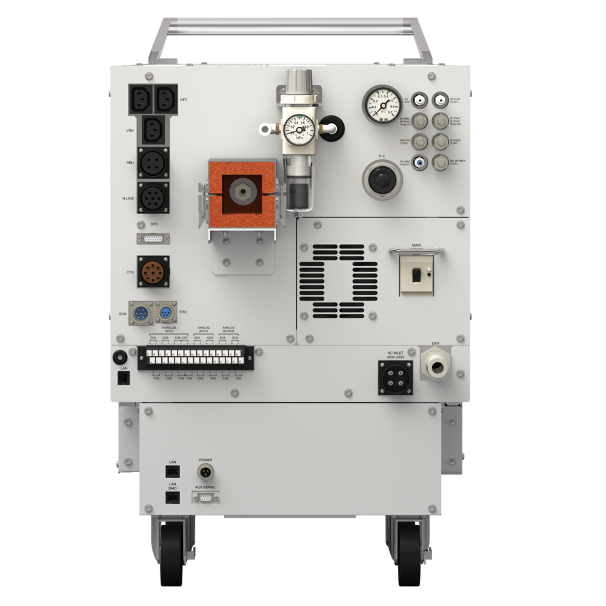
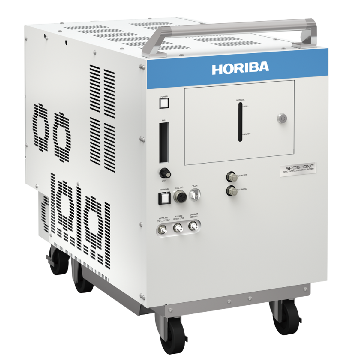
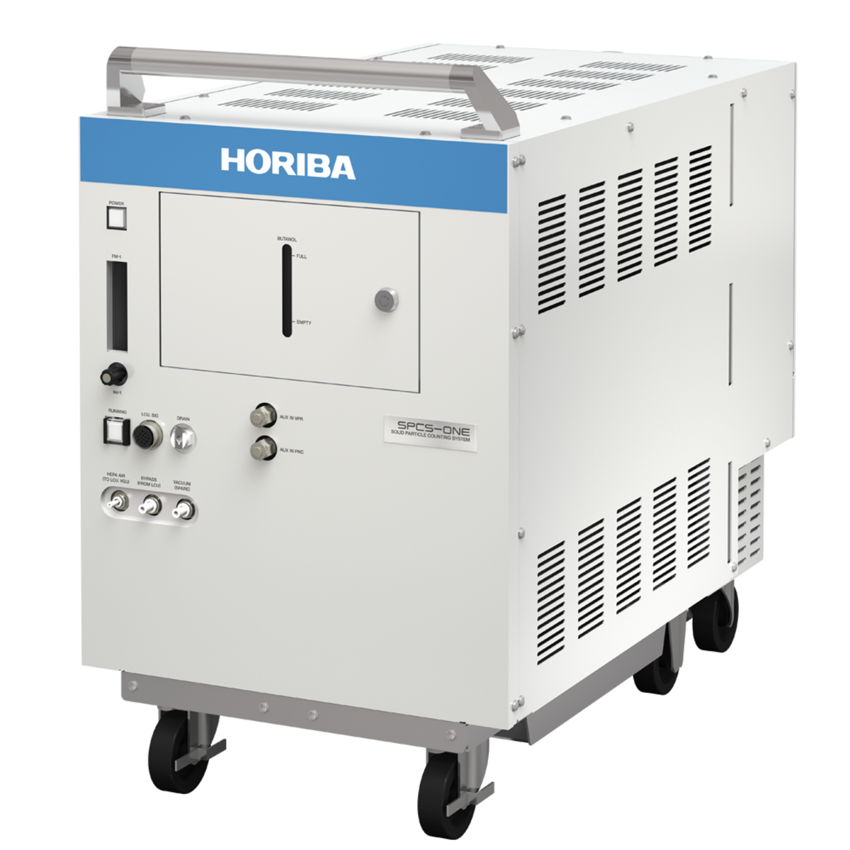
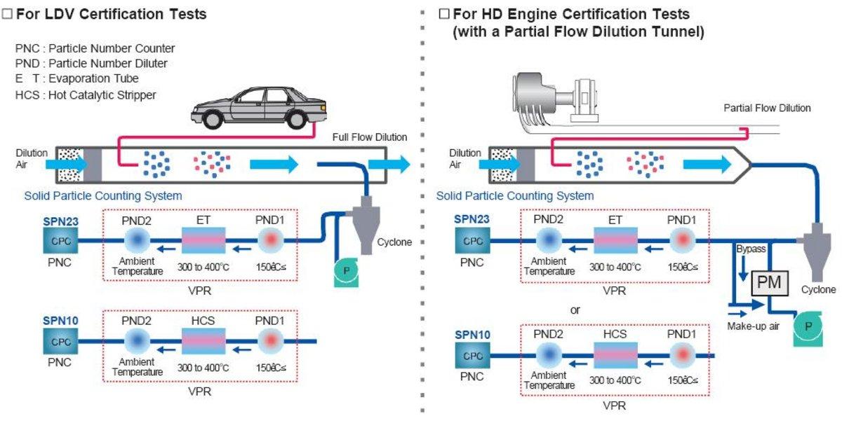
The HORIBA SPCS-ONE series measures solid particle number concentrations in real time. Configurations are available for SPN23 measurement down to 23 nm, SPN10 measurement down to 10 nm, or simultaneous SPN23 and SPN10 measurement.¹
Designed for certification testing and research and development, SPCS-ONE supports full-flow dilution, partial-flow dilution and direct-sampling applications. Its flexible configuration options support engine, vehicle, particulate-filter and brake-particle measurement requirements.
As part of HORIBA ONE PLATFORM, compatible SPCS-ONE systems can be operated and monitored alongside other HORIBA measurement equipment through a common software environment.
Key capabilities:
¹ For simultaneous SPN23 and SPN10 measurement, either an evaporation tube (ET) or a hot catalytic stripper (HCS) can be selected as the volatile-particle-removal unit. The two technologies cannot be used together. Contact HORIBA for details.
SPCS-ONE supports real-time SPN10 and SPN23 measurement for applicable emissions-certification procedures and advanced research and development. Flexible configurations allow particle-number measurement with full-flow dilution, partial-flow dilution, or direct sampling.
Applications include:

SPCS-ONE is available in four sampling configurations. Select the model according to the dilution system, sampling location and testing objective.
| Model² | Sampling Methods | ||
|---|---|---|---|
| Full-flow tunnel Certification applications using CVS | Partial-flow tunnel Certification applications using a partial-flow tunnel | Direct sampling Development applications using direct engine-exhaust sampling | |
| SPCS-ONE-DL series | Supported | Not supported | Not supported |
| SPCS-ONE-MT series | Supported | Supported | Not supported |
| SPCS-ONE-DR series | Supported | Not supported | Supported |
| SPCS-ONE-MD series | Supported | Supported | Supported |
| ² Model abbreviations: DL = Dilution; MT = with Micro Tunnel; DR = Direct; MD = with Micro Tunnel and Direct. | |||

SPCS-ONE can also support solid and total particle-number measurement in brake-emissions testing. When integrated with appropriate brake-dynamometer, sampling and test-automation equipment, the system helps engineers measure and evaluate particles generated by brake-pad and brake-disc wear.
Learn how HORIBA addresses brake wear, tire wear and other non-tailpipe particle sources with our non-exhaust and brake-emissions solutions.
See how particle counters, particulate-matter collectors and integrated test equipment support complete testing workflows on our brake-emission measurement analyzers page.


HORIBA ONE PLATFORM provides a common operating environment for SPCS-ONE and other compatible HORIBA measurement systems. Laboratories can control multiple systems from one PC, monitor equipment status and bring measurement data together for more efficient processing and analysis.
Discover how HORIBA ONE PLATFORM connects and manages laboratory measurement systems.
The compact SPCS-ONE main unit is designed for installation and movement between compatible test locations. Because operation can be centralized through HORIBA ONE PLATFORM, laboratories can relocate the measurement unit without moving a dedicated control PC.
ISO/IEC 17025-accredited calibration is available for selected models in supported regions.³ Calibration can be coordinated with maintenance, adjustment and other services to help reduce instrument downtime.
³ Availability varies by model and region. Contact HORIBA for details.
Optional units support regulatory checks, sample handling, higher-temperature environments and additional laboratory configurations.
| Optional unit | Application or function | Dimensions (W × D × H) and mass |
|---|---|---|
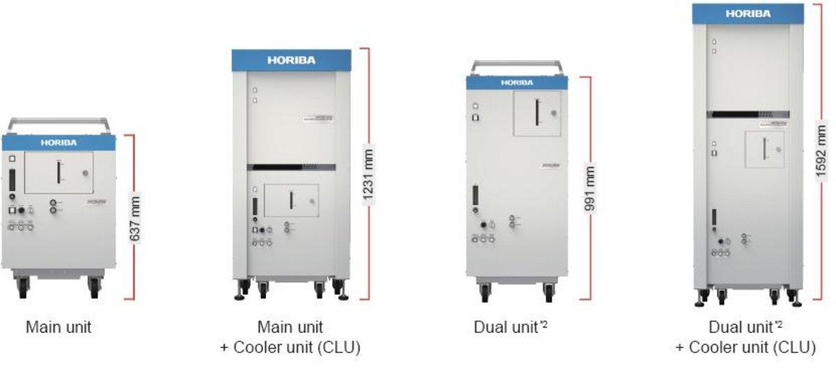
| Cooler Unit (CLU) | Supports high-temperature testing up to 45 °C | Main unit: 570 × 854 × 1,231 mm; approx. 160 kg. Dual unit: 570 × 854 × 1,592 mm; approx. 170 kg. |
| CPC Sample Flow Checker (CFC) | Automates CPC sample-flow checks required for monthly regulatory inspections | 170 × 245 × 60 mm; approx. 2 kg |
| Selector Cyclone Unit (SCU) | Allows two lines to be switched; a cyclone can be installed | 360 × 560 × 458 mm; approx. 40 kg |
| Cyclone Unit (CYU) | External cyclone⁴ | 290 × 146 × 236 mm; approx. 4 kg⁵ |
| Sample Return Unit (SRU) | Returns the sample to the full-flow tunnel⁴ | 303 × 588 × 469 mm; approx. 44 kg |
| Dilution Factor Checker (DFC) | Supports dilution-factor checks and flow-rate calibration | Stand-alone unit: 430 × 550 × 320 mm; approx. 38 kg⁶. With optional cabinet: 570 × 854 × 1,041 mm; approx. 130 kg. |
| Linearity Check Unit (LCU) | Generates solid particles for linearity and penetration-efficiency checks | 350 × 690 × 699 mm; approx. 35 kg |
⁴ Proposed when required for regulatory compliance.
⁵ Dimensions depend on customer specifications.
⁶ Stand-alone unit.
| Specification | SPCS-ONE-DL-23 | SPCS-ONE-MT-23 | SPCS-ONE-DR-23 | SPCS-ONE-MD-23 |
|---|---|---|---|---|
| Measuring principle | Laser-scattering condensation particle counting (CPC) | |||
| Measured component and range | Number concentration of solid particles: 0–10,000 up to 0–50,000 particles/cm3 after internal dilution2 | |||
| CPC counting efficiency | 50 ± 12% at 23 nm; greater than 90% at 41 nm | |||
| Sample-handling temperature | Dilute sampling: 52 °C or less Maximum permissible temperature for direct sampling: 350 °C3 | |||
| Diluted-sample temperature |
|
|
|
|
| Dilution factors |
|
|
|
|
| Particle Concentration Reduction Factor (PCRF) | 0.95 < fr (30 nm) / fr (100 nm) < 1.3 0.95 < fr (50 nm) / fr (100 nm) < 1.2 | |||
| Volatile-particle removal unit | Evaporation tube | |||
| Volatile-particle removal efficiency | Greater than 99.0% at a particle size of 30 nm and a concentration of 10,000 particles/cm3 or more | |||
| Dilution-factor accuracy | Within ±10% of the nominal dilution-factor setting4 | |||
| Operating environment | Without CLU (standard): Ambient temperature: 5–30 °C; relative humidity: 80% or less; altitude: 0–2,000 m above sea level (0–2,500 m with altitude simulation). With CLU (optional): Ambient temperature: 5–45 °C; relative humidity: 80% or less; altitude: 0–2,000 m above sea level (0–2,500 m with altitude simulation). | |||
| Power-supply voltage and frequency | 200/220/230/240 V AC (±10%, maximum 250 V), 50/60 Hz (±1.0 Hz), single-phase; specify when ordering | |||
| Power requirements | Main unit: Maximum 2.5 kVA Main unit and all optional units: Maximum 4.7 kVA | Main unit: Maximum 2.7 kVA Main unit and all optional units: Maximum 4.5 kVA | Main unit: Maximum 2.7 kVA Main unit and all optional units: Maximum 4.6 kVA | Main unit: Maximum 2.8 kVA Main unit and all optional units: Maximum 4.7 kVA |
| Dimensions5 and mass | 434 (W) × 731 (D) × 637 (H) mm Approximately 123 kg | 434 (W) × 910 (D) × 637 (H) mm Approximately 144 kg | 434 (W) × 845 (D) × 637 (H) mm Approximately 128 kg | 434 (W) × 910 (D) × 637 (H) mm Approximately 149 kg |
| Specification | SPCS-ONE-DL-10 | SPCS-ONE-MT-10 | SPCS-ONE-DR-10 | SPCS-ONE-MD-10 |
|---|---|---|---|---|
| Measuring principle | Laser-scattering condensation particle counting (CPC) | |||
| Measured component and range | Number concentration of solid particles: 0–50,000 particles/cm3 after internal dilution2 | |||
| CPC counting efficiency | 65 ± 15% at 10 nm; greater than 90% at 15 nm | |||
| Sample-handling temperature | Dilute sampling: 52 °C or less Maximum permissible temperature for direct sampling: 350 °C3 | |||
| Diluted-sample temperature |
|
|
|
|
| Dilution factors |
|
|
|
|
| Particle Concentration Reduction Factor (PCRF) | 0.95 < fr (15 nm) / fr (100 nm) < 2.0 0.95 < fr (30 nm) / fr (100 nm) < 1.3 0.95 < fr (50 nm) / fr (100 nm) < 1.2 | |||
| Volatile-particle removal unit | Hot catalytic stripper | |||
| Volatile-particle removal efficiency | Greater than 99.9% for C40 (count median diameter greater than 50 nm; mass density greater than 1 mg/m3) | |||
| Dilution-factor accuracy | Within ±10% of the nominal dilution-factor setting4 | |||
| Operating environment | Without CLU (standard): Ambient temperature: 5–30 °C; relative humidity: 80% or less; altitude: 0–2,000 m above sea level (0–2,500 m with altitude simulation). With CLU (optional): Ambient temperature: 5–45 °C; relative humidity: 80% or less; altitude: 0–2,000 m above sea level (0–2,500 m with altitude simulation). | |||
| Power-supply voltage and frequency | 200/220/230/240 V AC (±10%, maximum 250 V), 50/60 Hz (±1.0 Hz), single-phase; specify when ordering | |||
| Power requirements | Main unit: Maximum 2.5 kVA Main unit and all optional units: Maximum 4.7 kVA | Main unit: Maximum 2.7 kVA Main unit and all optional units: Maximum 4.5 kVA | Main unit: Maximum 2.7 kVA Main unit and all optional units: Maximum 4.6 kVA | Main unit: Maximum 2.8 kVA Main unit and all optional units: Maximum 4.7 kVA |
| Dimensions5 and mass | 434 (W) × 731 (D) × 637 (H) mm Approximately 123 kg | 434 (W) × 910 (D) × 637 (H) mm Approximately 144 kg | 434 (W) × 845 (D) × 637 (H) mm Approximately 128 kg | 434 (W) × 910 (D) × 637 (H) mm Approximately 149 kg |
1 Model abbreviations: DL = Dilution; DR = Direct; MT = with Micro Tunnel; MD = with Micro Tunnel and Direct.
2 Determine the system dilution factor so that the particle concentration after dilution remains within the measuring range.
3 The allowable gas-temperature range at the sample-probe inlet depends on the sampling conditions because the DSU diluter temperature is limited to 350 °C or less. Please contact HORIBA for details.
4 Accuracy of the dilution-factor check using span gas.
5 Dimensions and mass exclude the transfer tube, control unit and optional units.
Do you have any questions or requests? Use this form to contact our specialists.