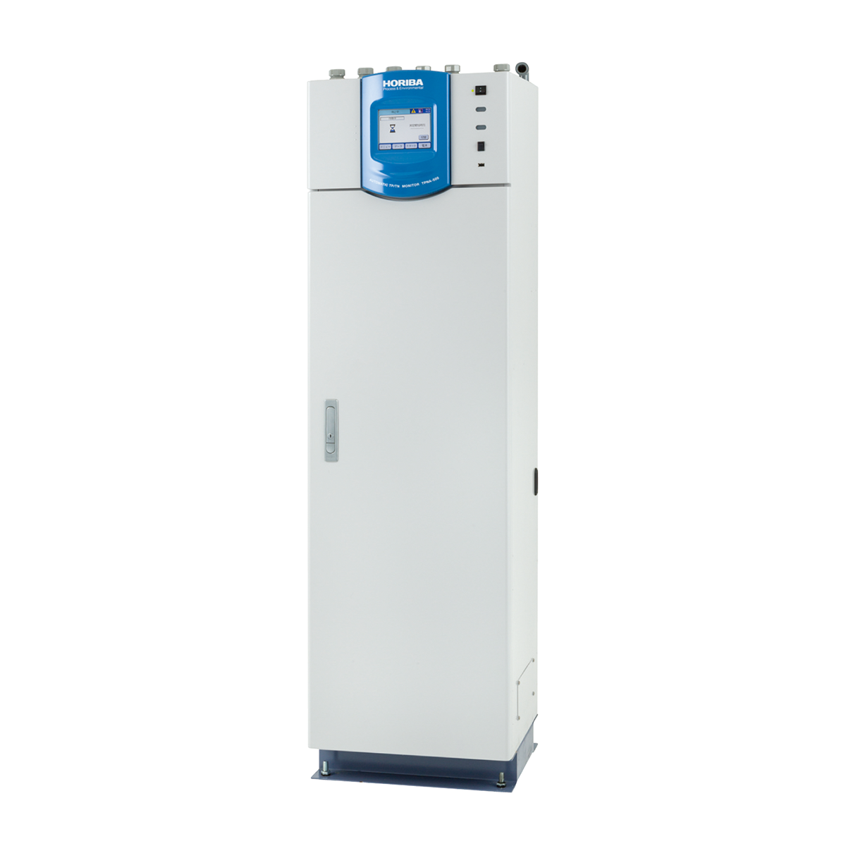
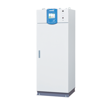
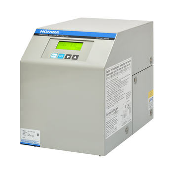
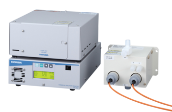
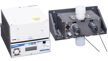
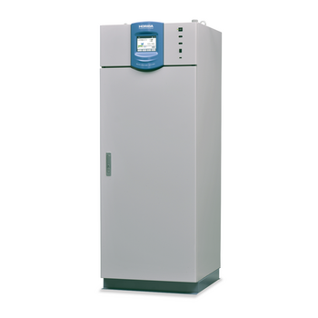
| General specifications | Equipment name | Automatic total nitrogen/phosphorus monitoring system | |
|---|---|---|---|
| Model | TPNA-500 | ||
| Dimensions *1 | 460 (W) mm × 385 (D) mm × 1600 (H) mm | ||
| Mass | Approx. 87 kg | ||
| Power supply | 100 V to 240 V AC ±10%, 50 Hz/60 Hz | ||
| Power consumption | 100 V to 240 V AC: Approx. 250 VA | ||
| Performance | Measurement range *2 | Total nitrogen: 0 mg N/L to 2/5/10/20/50/100/200/500/1000 mg N/L Total phosphorus: 0 mg P/L to 0.5/1/2/5/10/20/50/100/250 mg P/L | |
| Repeatability | Within ±3% of the full scale (Total nitrogen full scale: 50 mg N/L or less, total phosphorus full scale: 10 mg P/L or less) Within ±5% of the full scale (Total nitrogen full scale: 100 mg N/L to 1000 mg N/L, total phosphorus full scale: 20 mg P/L to 250 mg P/L) Both with standard solution | ||
| Measurement principle | Total nitrogen: Alkaline potassium persulfate, ultraviolet oxidative dissolution - ultraviolet absorption spectrophotometry Total phosphorus: Potassium persulfate, ultraviolet oxidative dissolution - Molybdenum blue spectrophotometric method | ||
| Number of measurement points | One point (standard), two points (option) | ||
| Number of measurement ranges *3 | One range (standard), 2 ranges (option) | ||
| Measurement cycle | 60 min | ||
| Installation conditions | Ambient temperature | 2℃ to 40℃ | |
| Ambient humidity | Relative humidity 85% or less (no condensation) | ||
| Ambient environment |
| ||
| Measurement conditions | Sample water conditions *4, *5, *6,*7 | Temperature | 2℃ to 40℃ (no freezing) |
| Flow rate |
| ||
| Pure water/tap water supply conditions*8 | Amount of usage | 43 L/month (depending on the measurement range) | |
| Water quality |
| ||
| Supply method | Supply by the tank (standard) or continuous supply by the pure water equipment (option) | ||
| Supply pressure | 0.1 MPa to 0.5 MPa | ||
| Input/output specifications | Analog output | Number of points | Standard: 4 points Option (3-component specification/2-point meter specification): 8 points |
| Type | Standard: 4 mA to 20 mA DC, 0 mA to 16 mA DC (Set to 4 mA to 20 mA DC at the factory. It can be switched to 0 mA to 16 mA DC from the screen.) Option: 0 V to 1 V DC, 1 V to 5 V DC | ||
| Description | Standard: TN concentration, TP concentration, TN load, TP load, flow rate per hour Option (3-component specification): COD concentration, COD load, COD instantaneous concentration Note: The COD output settings depend on the equipment conditions. | ||
| Output impedance | 500Ω or less | ||
| Contact output | Number of points | Standard: 16 points Option (3-component specification/2-point meter specification): 22 points | |
| Type | No-voltage output contact | ||
| Form | Isolated output | ||
| Output capacity | 250 V AC 3 A 30 V DC 3 A (Only 30 V DC 3 A is available for the “Maintenance” contact) | ||
| Status output | Meas., Calibration, Standby, Maintenance, SYNCHRONOUS IDLE 1, SYNCHRONOUS IDLE 2, Power, etc. | ||
| Alarm output | Hi limit alarm (TP, TN, COD), H.Hi limit alarm (TP, TN, COD), Load limit alarm (TP, TN, COD), Sample Lack, Lack Blank, Lack Reag., Lack Span, Full Drain Tank, Total Alarm 1 to 6, various meter errors, etc. | ||
| Analog input | Number of points | Standard: 1 point Option (3-component specification/2-point meter specification): 2 points | |
| Type | Standard: 4 mA to 20 mA DC Option: 1 V to 5 V DC | ||
| Description | Flow rate (full scale can be set as desired), UV/COD meter concentration | ||
| Contact input | Number of points | Standard: 9 points Option (3-component specification/2-point meter specification): 18 points | |
| Type | No-voltage a contact input (open collector is available) | ||
| Form | Isolated input: Common to the (-) side | ||
| ON resistance | 100 Ω (max.) | ||
| Open-circuit voltage | 26 V DC (max.) | ||
| Short-circuit current | 13 mA DC (max.) | ||
| Function | Meas. Start, Cal. Start, Modify Date, Line Select, Flow Mainte, Flow Err., Flow Power, Flow No Drain, UV/COD Mainte, UV/COD Err., UV/COD Power, etc. | ||
| Equipment function | Display | Touch panel type liquid crystal (color) | |
| Load calculation function | Standard: TP/TN load calculation function is provided Option: COD and 2-point meter load calculation function are provided | ||
| Option | Turbidity compensation function is provided (TN) (Turbidity compensation wavelength: 275 nm) | ||
| Memory function | Measurement value: Memory for over 1 year (including the daily and hourly reports) Alarm history: 500 events Calibration history: 100 events Operation history: 100 events Note: USB external memory device can be used. | ||
| Communication function | Standard: RS-485 Option: RS-232C | ||
| Communication protocol | Modbus | ||
| Printer | Provided (recording paper width: 58 mm) With automatic take-up equipment | ||
| Reagent | Reagent A | 0.8 mL per measurement (capacity: 1000 mL) | |
| Solution B | 0.2 mL per measurement (capacity: 250 mL) | ||
| Solution C | 0.1 mL per measurement (capacity: 250 mL) | ||
| Solution D | 0.1 mL per measurement (capacity: 250 mL) | ||
| Solution E | 0.19 mL per measurement (capacity: 250 mL) | ||
| Solution F | 0.2 mL per measurement (capacity: 250 mL) | ||
| Span solution | 50 mL per measurement (capacity: 1000 mL) | ||
| Replacement cycle | One month (only under certain storage/usage environment) | ||
*1: Compatible with older products: Model TPNA-300, PN-100 series channel base (standard)
*2: Full-scale values for both total nitrogen and total phosphorous must be greater than or equal to 0.2 and less than or equal to 100
*3: When the first range is set to low concentration, the following condition must be met for the same measurement component:
1 ≦ Second range full scale/first range full scale ≦ 50
*4: The chemical cleaning function for the sample line can be selected according to the nature of the sample
*5: The provided overflow tank can be installed in either the left/right side or rear of the main unit
*6: The distance from the provided overflow tank to the main unit should be within 1 m
*7: The sample must not contain the components that could affect the measurement (metallic ions, etc.)
*8: When tap water is supplied, flush the pipes by running the water for approximately 30 minutes before supplying.
Note
Perform the installation work while taking the features of the analyzer into consideration. Also, ensure an environment in which the equipment can operate normally. If the equipment is not operating normally due to impairment, operating conditions, or other unexpected events, take appropriate action so that no damage to the equipment will occur.
