Engine testing in automobiles and components


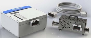
Micro Dilution Tunnel
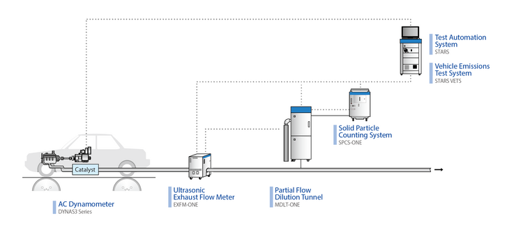
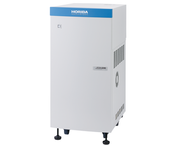
The MDLT-ONE is designed to sample particulate emissions using the partial flow dilution method. A small portion of the total exhaust is diluted with HEPA* filtered air to create a constant flow rate through particulate filters to collect Particulate Matter (PM). Compliant to the latest regulations, the new MDLT-ONE is very compact and offers faster response by the use of high precision venturi flow meters and a piezo actuated valve.
*HEPA: High Efficiency Particulate Air
Heated filter system and flow controllers installed in a single rack. Swivel connection of tunnel section to cabinet allows flexible installation.
Flow weighting (EPA-approved technology)
Allows user to collect PM on a single filter over all three phases of FTP by adjusting sampling flow rate over the filter to weight the filter face velocity over the three phase of the FTP based on weighting targets. This EPA-approved technology increases the measurement accuracy for meeting the upcoming CARB LEV III 1`mg/mile emission limit and reduces filter weighing cycles from three to one, eliminating manual checks and calculations.
Automatic filter changer
Increases testing efficiency, allowing a maximum of 28 tests to be run without manual intervention. This feature can be mounted in the main rack to keep equipment footprint small.
Automatic calibration software enhances accuracy and ease of use
The MDLT-ONE series performs automatic calibration by flowing air in-series through two venturi flow meters and correcting any difference to zero in the software. This can be included in an automated sequence within a test template.
Integrated Operating Platform
HORIBA ONE series systems employ a common use interface, “HORIBA ONE PLATFORM” offering future expandability and ease of integration into test automation systems.

PM Emission Measurement of All Engines
R&D Support of Engine and After Treatment System

ISO-16183 | EU: Euro VI (HDV) | US: 40 CFR Part 1065/1066 |
Japan: Post new long term | EU: Stage IV / V (NRMM) |
|
| System outline | ||||||
| PM sampling method | Partial flow dilution method | |||||
| Control modes for dilution | Proportional sampling mode (Const. split ratio)/ Fixed dilution ratio mode (Const. dilution ratio)/ Fixed flow rate mode (Manual control) | |||||
| Control methods for dilution | ・Real-time control based on analog input of exhaust flow rate ・Control based on learned pattern of exhaust rate | |||||
| Required signal for gas sampling | Isolated analog signal (0 to 10 V) | |||||
| Flow rate of diluted gas | 25 to 80 L/min*1 (under the condition of 20 °C and 101.3 kPa) | |||||
| Accuracy of dilution ratio | Within ± 5 % (Confirmed by measuring CO₂) When dilution ratio=15 rate at 20 °C and 101.3 kPa: 53 to 80 L/min | |||||
| PM mass calculation*2 | PM mass (in g/test or g/kWh) can be calculated and saved, based on integrated values of flow rated and dilution ratio. | |||||
| Configurations | ||||||
| System configuration | ・Main unit: Dilution-tunnel unit ・Operation unit: PC, monitor, keyboard and mouse (table is not included) | |||||
| Utilities | ・Purified air: for dilution gas, 400 to 700 kPa, oil free, at least 100 L/min (at 20 °C and 101.3 kPa) | |||||
| Power supply voltage and frequency | ・Main unit: 100/110/120/200/220/230/240 V AC, 50/60 Hz, single phase ・Operation unit: 100/110/120/200/220/230/240 V AC, 50/60 Hz, single phase | |||||
| Power requirements | Main unit: Max. 3.0 kVA / Operation unit: Max. 0.5 kVA | |||||
| Dimensions | ・Main unit: 570 (W) × 730 (D) × 1700 (H) mm ・Space for operation unit: 900 (W) × 500 (D) mm (table is not included) | |||||
| Mass | Main unit: Approx. 300 kg (excluding operation unit) | |||||
| Number of filter lines | Max. 6 lines (5 for sample, 1 for bypass) | |||||
| Type of filter holder | ・φ70 mm type: actual PM sampling area φ60 mm, with back-up filter ・φ47 mm type: actual PM sampling area φ38.8 mm*1, with back-up filter*1 | |||||
| Operating conditions | ||||||
| Sampling Pressure | Between atmospheric pressure and up to 40 kPa Back pressure of exhaust line: Less than 1 kPa | |||||
| Options | ||||||
| Filter auto-changer*3 | Changer for automatic replacement of PM filter (φ 47 mm) | |||||
| Valve switching | Additional air valve before filter (Replacement of sampling filter on bypass mode) | |||||
| HOST interface*3 | LAN communication using a 10 Base T port Conforms to IEEE802.3 (ISO880 2/3) | |||||
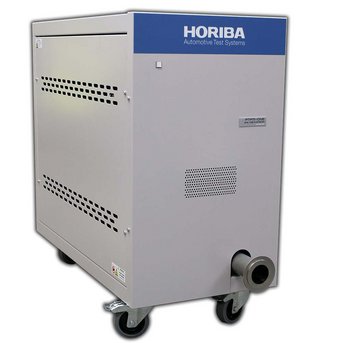
| Conditioner for dilution air / Compressor | ||||||
*1, For the filter face velocity in the regulations (less than 100 cm/s), the flow rate for the φ47 mm filter must be 65 standard L/min.
*2, Input the amount of PM collected on filter to calculate PM mass. It is necessary to input engine output (kW) to calculate the PM mass engine output (g/kWh).
*3, Please contact HORIBA, when you order.

Do you have any questions or requests? Use this form to contact our specialists.
")
Flow Type
")
Electrode for Low-Volume Samples

Constant Volume Sampler

Ultrasonic Exhaust Flow Meter
FTIR Exhaust Gas Analyzer Dilute Measurement Type
FTIR Exhaust Gas Analyzer Direct Measurement Type

Heated Type NOx Analyzer

Heated Type THC Analyzer

Motor Exhaust Gas Sulfur Analyzer

Motor Exhaust Gas Analyzer

Solid Particle Counting System
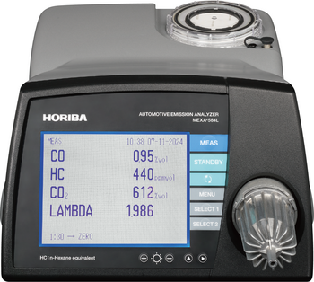
Automotive Emission Analyzer

Air-to-fuel Ratio Analyzer

Motor Exhaust Gas Analyzer for Engine & Vehicle Testing

FTIR Motor Exhaust Gas Analyzer

Laser Spectroscopic Motor Exhaust Gas Analyzer

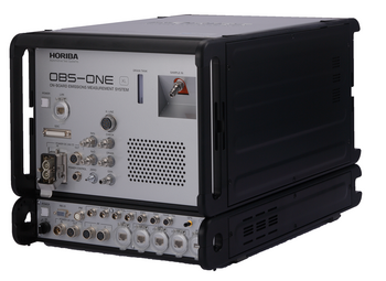
On-board Emissions Measurement System

On-board Emissions Measurement System

On-board Emissions Measurement System
On-board SPN10 measurement for real-world
On-board NH3/N2O Measurement System for real-world driving

Particulate Filter Management System
Pitot Tube Exhaust Flow Meter
Dual Pitot Tube Exhaust Flow Meter

Road-to-Rig Chassis Dyno Replication
