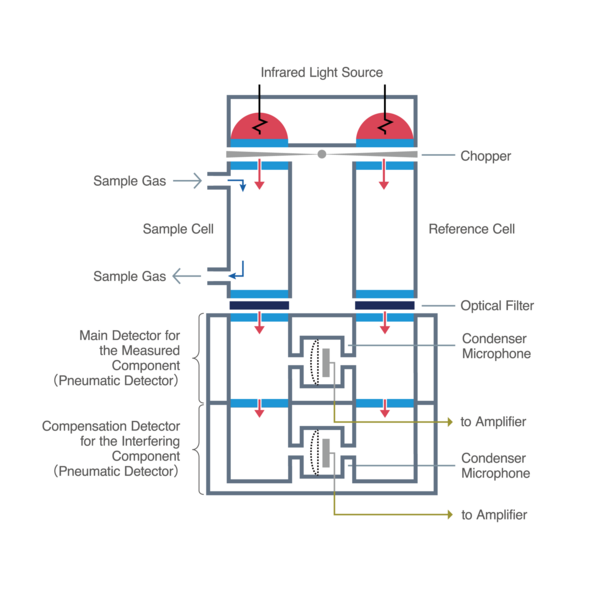
Structure and Operating Principle of Infrared Gas Analyzer

Actual Infrared Gas Analyzer Structure and Component Functions

Figure 6 shows an example of an actual infrared gas analyzer structure. It consists of a combination of major parts with the functions listed in Table 1.

Figure 6: Structure of infrared gas analyzer

Main Components and Functions (Table 1)

Table 1: Main Components and Functions
1) Infrared light sourceEmits infrared radiation light containing wavelengths in mid-infrared radiation of 2.5-25μm
2) Chopper  

Intermittent infrared radiation supplied from infrared lights source to a sample cell and a reference cell at a regular cycle (A type of modulation mechanism)

3) Sample cell, Reference cellThe sample cell is a gas cell that flows sample gas containing the measured component. The reference cell is a gas cell that flows reference gas or is enclosed, and it becomes an optical path for infrared radiation.
4) Optical filterA multi-layered membrane filter that transmits only infrared radiation of the absorbed specific wavelength of the measured component 
5) Main detector for the
measured component
Detection mechanism including sensors to detect changes of the infrared absorption of the measured component
6) Compensation detector for the
interfering component
Detection mechanism, including sensors, to detect changes of the infrared absorption of interfering component to compensate the influence of interfering component for the measured component
7) Signal processingSignal processing for the detected singnals of 5 and 6 to calculate the concentration of the measured component


Main Components and Configuration of Infrared Gas Analyzer

Photo 1 : Example of an infrared gas analyzer configurated with main components

Photo 1 : Example of an infrared gas analyzer configurated with main components

Photo 1 shows an example of an infrared gas analyzer configurated with main components. To respond quickly to various market needs, HORIBA manufactures the key components of an infrared gas analyzer in-house: infrared light source, sample cell, reference cell, optical filter, and detector.

Operating Principle of an Actual Infrared Gas Analyzer

This section explains the operating principles of the actual infrared gas analyzer. The basic structure of the infrared gas analyzer (Figure 4) incorporates a reference cell, a chopper, and a pneumatic detector (Figure 5), and can measure gas concentration by using the three main functions in table 2(Figure 6, Photo 1).

Table 2: Key Features Comprising an Infrared Gas Analyzer
1) Detection Function of the Measured ComponentDetects infrared radiation absorbed corresponding to measured component in the sample gas
2) Modulation Function  

To improve the measurement accuracy, the infrared radiation from the infrared light source is intermittent at a regular interval, and the detector signal is output as a modulated signal.

3) Compensation Function for Interfering ComponentDetect infrared absorption corresponding to the concentration of the interfering component to compensate for interfering component effects on the measured component

This section describes the operating principle in the case where the sample gas is exhaust gas, and CO in the exhaust gas is measured.

1)Detection Function of the Concentration of the Measured Component

Two gas cells (sample cell and comparison cell) are used. The difference in the amount of infrared absorption generated in each gas cell based on the NDIR measuring principle is detected as a pressure difference by a condenser microphone in the pneumatic detector, and measure the concentration of the measured component in the sample gas by using the pressure difference. The detector for measuring the concentration of the measured component  is called the main detector for the measured component (Figure 6).

Functions and Operations of the Sample Cell, Reference Cell and Condenser Microphone (Figure 7)

Figure 7: Basic Operating Principle of Analyzer

Inside the pneumatic detector (Figure 5), CO, a measured component, is contained in both chambers separated by a condenser microphone diaphragm. The diaphragm of the condenser microphone in the detector moves due to the pressure difference between the two chambers, changing capacitance of a capacitor formed with this diaphragm and the back plate, and the pressure difference is detected as an electrical signal.

In the reference cell, an inert gas such as N2 that does not absorb infrared radiation is enclosed. In this cell, infrared radiation is not absorbed and only the infrared radiation of absorbing wavelength for CO is transmitted through the optical filter and enters the right chamber of the detector below the reference cell. The enclosed CO absorbs  transmitted infrared radiation and generates heat, which increases the chamber pressure and constantly pushes the diaphragm at a constant pressure.

On the other hand, infrared radiation is absorbed in the sample cell depending on the CO concentration in the exhaust gas. The infrared radiation of a specific wavelength after being absorbed in the sample cell, is selectively transmitted by the optical filter for the infrared absorption wavelength of CO and enters the left chamber of the detector below the sample cell, pushing the diaphragm at a pressure corresponding to the amount of infrared radiation absorbed by the CO enclosed in the left chamber. At this time, the diaphragm moves by the pressure difference between the left and right chambers (not moving or moving to the leftchamber. As for pressure, left chamber ≦ right chamber). This pressure difference is converted and output to an electrical signal as the infrared absorption of CO in the exhaust gas, which is converted to a CO gas concentration value by the signal processing unit.

2)Modulation function

The condenser microphone detects the change in capacitance when there is a difference in distance between the diaphragm and the back plate that changes in correspondence to the pressure difference between the left and right side of the diaphragm. Even when the concentration of the measured component gas changes little and the movement of the diaphragm is small and slow, the infrared radiation from the infrared light source is interrupted at a regular interval to vibrate the diaphragm at a regular interval, and the minute concentration change can be accurately measured. This sequence of operations is called modulation.

Function and Operation of the Chopper

Figure 8: Chopper Operation vs. Infrared Supply

Specifically, it is a mechanism that rotates a thin plate like a bow-tie called a chopper under an infrared light source, which performs the modulation operation (Figure 8).

By rotating this thin plate, the amount of infrared radiation of each infrared light source of sample cell and reference cell changes continuously from 0% to 100% periodically. For example, if the chopper completely overlaps the infrared light source of both cells (rotational angle: 0 degrees), no infrared radiation is generated in both cells, and the condenser microphone diaphragm does not inflate. Conversely, when there is no overlap (rotation angle: 90 degrees), 100% infrared radiation from the infrared light source is supplied to both cells.

Figure 9: Operation of Infrared Gas Analyzer and Detection of Concentration Signals of Measured Component

By combining 1) and 2), it is possible for the condenser microphone to detect the differential lateral-pressure proportional to the concentration of measured component (CO in the exhaust gas) flowing to the sample cell (Figure 9).

3)Compensation Function for Interfering Component (Figure 10)

Among the gases other than the measured component contained in the sample gas, some gases with wavelengths that overlap with the infrared absorption wavelength of the measured component may coexist. This gas is called an interfering component. (Figure 10 graph: infrared absorption wavelengths and amounts of infrared absorption for the measured component and the interfering component) When the interfering component coexists, the main detector for the measured component output-signal includes infrared radiation absorbed by interfering component, so this effect must be removed. To remove this effect, the compensation detector for interfering component detects infrared absorption corresponding to the concentration of interfering component in the sample gas.

Function and Operation of the Compensation Detector for Interfering Component

Figure 10: Compensation detector for the interfering component and obtaining the measured component signal after correction for interference effect

The compensation detector for the interfering component is placed so that the same infrared radiation optical path and modulation function as the main detector for the measured component (Figure 10). The detector for interfering compensation is also the same type of pneumatic detector (Figure 5) as the main detector for the measured component. The remaining infrared radiation absorbed by measured component and interfering component in main detector for the measured component is transmitted to compensation detector for the interfering component. This transmitted infrared radiation is absorbed by the interference-correction gas enclosed in the compensation detector for interfering component and is detected by the condenser microphone as a pressure difference. This detects a correction signal (B) corresponding to the concentration of interfering component (Figure 10 graph Signal for correction of interfering component). By subtracting the output signal (B) of the compensation detector for interfering component from the output signal (A) of the main detector for measured component in the signal processing, the concentration of the measured component with interference-correction can be obtained.

Pedido de Informação

Você tem alguma dúvida ou solicitação? Utilize este formulário para entrar em contato com nossos especialistas.

* Esses campos são obrigatórios.

Corporate