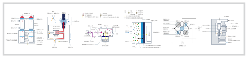
Estrutura e princípio de funcionamento (Figuras 14-1 e 14-2)
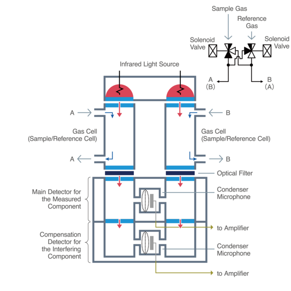
Ao contrário da modulação convencional com um chopper, este método utiliza uma válvula solenoide para alternar, em intervalos regulares, a introdução de gás de amostra e gás de referência na mesma célula de gás. Assim, a válvula solenoide realiza o mecanismo de modulação. Um exemplo da estrutura de um analisador para este método é mostrado na Figura 14-1.
Enquanto a modulação pelo chopper altera a quantidade de luz infravermelha fornecida às células de amostra e de referência, o método modulação cruzada altera o fluxo de gás para as células de amostra e de referência. Com exceção do mecanismo de modulação, a função de detecção do componente medido e a função de compensação do componente interferente, necessárias para detectar a concentração do componente medido, são as mesmas do analisador de gás infravermelho descrito até agora. Portanto, esta seção se concentra na operação do mecanismo de modulação (Figura 14-2).

Figura 14-2: Princípio de operação de modulação do método de modulação cruzada
A unidade de válvula solenoide permite que o gás da amostra flua para a célula de gás esquerda e o gás de referência flua para a célula de gás direita simultaneamente. Se houver componente gasoso a ser medido no gás da amostra, o diafragma do microfone de condensador se expandirá para o lado esquerdo (em direção à célula da amostra) (Figura 14-2, figura à esquerda).
Em seguida, a unidade da válvula solenoide é acionada e o gás da amostra flui para a célula de gás da direita, enquanto o gás de referência flui simultaneamente para a célula de gás da esquerda.
Se houver componente gasoso mensurável no gás da amostra, o diafragma do microfone de condensador se expandirá para o lado direito (em direção à célula de amostra) (Figura 14-2, figura à direita).
Esta operação é repetida em um ciclo regular para modular o sinal de detecção do microfone de condensador. Ao movimentar o diafragma do microfone de condensador no detector para os lados esquerdo e direito, este método obtém o dobro do sinal detectado em comparação com o uso de um modulador de frequência (chopper), melhorando assim a imunidade a ruídos. Além disso, um mecanismo de fluxo de gás de amostra e de referência através de cada célula de gás para medição resulta em medições estáveis ao longo do tempo, reduzindo a influência da degradação das fontes de luz infravermelha e da contaminação das células de gás nos sinais de detecção.
 analyzer")
 analyzer")
 analyzer")
 analyzer")