Size:
1.77
MB
〈Catalog〉Industrial Water Quality Measuring Instruments
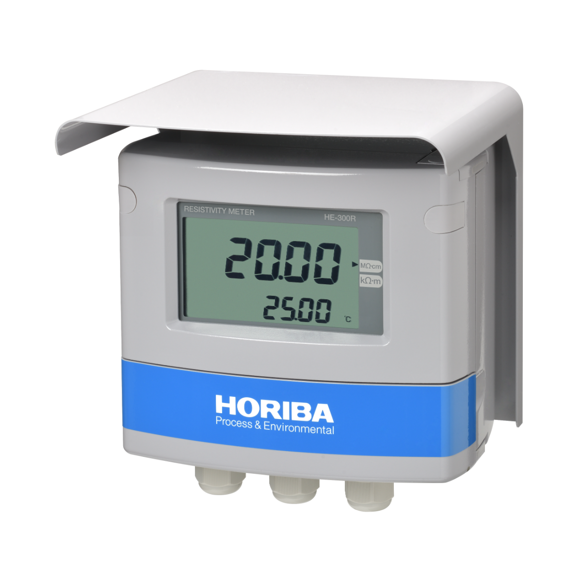
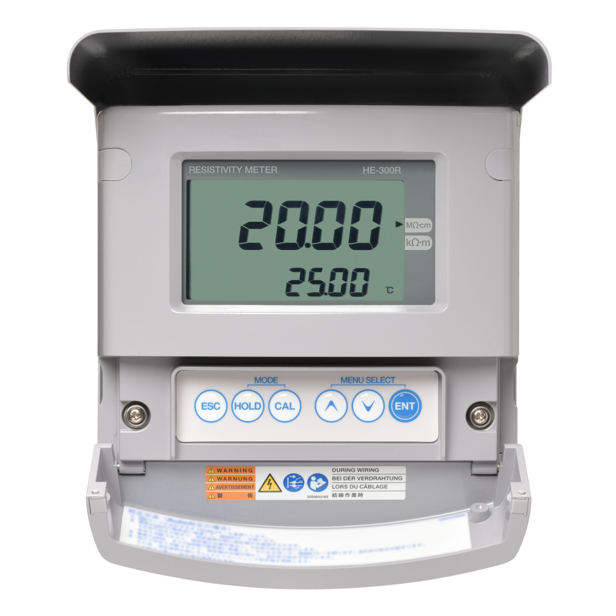
Field-installation type electric resistivity meter (resistivity meter)
Combined with the electric resistivity sensor (ERF series), it measures the electric resistivity and temperature of aqueous solutions. Suitable for measuring electric resistivity of UPW.
![]()
![]()
![]()
![]()
![]()
Enables measurements with minimal error
Measurements are affected less by ambient temperature and sample temperature, enabling accurate measurements with less error.
We provide equipment and sensor calibration services
Temperature sensor offset calibration is offered as well as transmitter and sensor combination calibration services. *Option
Highly responsive temperature sensor
Helps to minimize fluctuations in measurement values due to delayed temperature compensation in the event of sudden changes in water temperature.
| Product name | Resistivity meter | |||
|---|---|---|---|---|
| Model | HE-300R | |||
| Sensors in combination | 2-electrode method resistivity sensor (ERF-001 Series) of cell constant 0.01/cm | |||
| Measuring range | Resistivity | MΩ•cm | 0.000 to 2.000 | 0.00 to 20.00 (*1) |
| kΩ•cm | 0.00 to 20.00 | 0.0 to 200.0 (*1) | ||
| Temperature | ℃ | 0℃ to 100℃ (Display range: −10℃ to 110℃) | ||
| Display resolution | Resistivity | As shown in the measuring table. | ||
| Temperature | 0.01℃ | |||
| Performance | Resistivity | Repeatability | Within ±0.1% of the full scale (response for equivalent input) | |
| Linearity | Within ±0.5% of the full scale (response for equivalent input) | |||
| Temperature | Repeatability | ±0.1℃ (response for equivalent input) | ||
| Linearity | ±0.5℃ (response for equivalent input) | |||
| Transmission output | Output type | 4 mA to 20 mA DC: input/output isolated type | ||
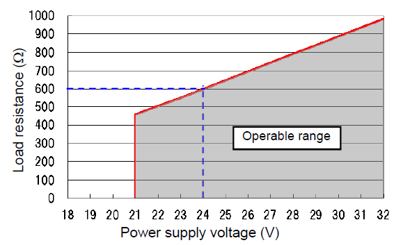
| Load resistance | Maximum: 600Ω Case of 24 V DC power supply | |||
| Linearity | ±0.08 mA (output only) | |||
| Repeatability | ±0.02 mA (output only) | |||
| Output range | Resistivity: Free setting within a measuring range. | |||
| Occasional out for error | Hold or burnout to either 3.8 mA or 21 mA | |||
| Transmission hold | In the maintenance mode, transmission signal is held at the latest value or preset value. In the calibration mode, transmission signal can be alive or held. | |||
| Contact input | Number of input | 1 | ||
| Contact type | No-voltage "a" contact for open collector | |||
| Conditions | ON resistance: 40 Ω max. Open voltage: 1.2 V DC Short-circuit current: 21 mA max. | |||
| Contact function | External input for transmission holding. | |||
| Temperature compensation | Applicable temperature element | Platinum resistor: 1 kΩ (0℃) | ||
| Compensation method |
| |||
| Temperature compensation range | 0℃ to 100℃ (However, the compensation calculation is extended lower than 0℃ or higher than 100℃.) | |||
| Calibration | Resistivity | Based on parameter input of coefficient for the sensor cell constant. | ||
| Temperature | Comparison to the accurate thermometer Both deviation and coefficient of RTD are taken into account for calibration. | |||
| Other function | UPW standard resistivity input | Select one from the next. 182.3 kΩ•m (standard), 181.8 kΩ•m, 182.4 kΩ•m, 18.23 MΩ•cm (standard), 18.18 MΩ•cm, or 18.24 MΩ•cm | ||
| Clipping function | If the measured value exceeds the user setting value for clipping, the measured data will be held at the clipping value. | |||
| Self-check | Electrode diagnostic error | Temperature sensor short-circuit, temperature sensor disconnection, and out of the temperature measurement range | ||
| Meter error | CPU, ADC, and memory errors | |||
| Operating temperature range | −20℃ to 60℃ (without freeze) | |||
| Operating humidity range | Relative humidity: 5% to 90% (without condensation) | |||
| Storage temperature | −25℃ to 65℃ | |||
| Power supply | Rated voltage | 24 V DC (operating voltage range: 21 V to 32 V DC) | ||
| Power consumption | 0.6W max. | |||
| Compatible standards | CE marking | EMC directive: EN61326-1 RoHS Directive: EN50581 | ||
| Immunity Industrial electromagnetic environment | Electostatic discharge | IEC61000-4-2 | ||
| Electromagnetic field of radiated radio frequency | IEC61000-4-3 | |||
| Electric fast transient/burst | IEC61000-4-4 | |||
| Surge | IEC61000-4-5 (*3) | |||
| Conducted interference induced by radio frequency | IEC61000-4-6 | |||
| Emission ClassA | Radiated disturbance | CICPR 11 CLASS A | ||
| Noise terminal voltage | CISPR 11 CLASS A | |||
| FCC Rules | Part15 CLASS A | |||
| Structure | Installation | Outdoor installation type | ||
| Installation method | Mount on 50 A pole or wall | |||
| Protection code | IP65 | |||
| Case material | Aluminum alloy (coated with epoxy-denatured melamine resin) | |||
| Material of fittings | SUS304 | |||
| Material of cover | SUS304 stainless steel (coated with epoxy-denatured melamine resin) | |||
| Material of display window | Polycarbonate | |||
| Display element | Reflective monochrome LCD | |||
| External dimensions | 180 (W) × 155 (H) × 115 (D) mm (excluding mounting brackets) | |||
| Mass | Main body: Approx. 2.8 kg; cover and mounting brackets: Approx. 1 kg | |||
Relation between power supply voltage and load resistance
Do you have any questions or requests? Use this form to contact our specialists.