Structure and Operating Principle of Gas Analyzer Using NDIR

Analyzers using NDIR are called infrared gas analyzers and are widely used for measurement due to their simple structure, easy maintenance, and features suitable for continuous measurement. HORIBA offers a broad lineup of infrared gas analyzers that can respond to market trends and the diverse requirements of on-sites applications.

Infrared Gas Analyzer Structure and Operating Principle

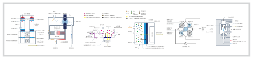
Figure 4: Basic construction and operating principles of infrared gas analyzer

The sampled gas (sample gas) flows into a gas cell, called a sample cell, where it is irradiated by infrared radiation from an infrared light source, causing the various gas molecules in the sample gas to absorb infrared radiation of each specific wavelength corresponding to their gas concentration.

The optical filter transmits to the detector only specific infrared radiation absorbed by the gas component to be measured in the sample cell. The detector is filled with the measured component's gas and the infrared radiation transmitted through the optical filter is absorbed by the gas molecules (measured component) in the detector. The absorbed energy increases the vibration of the gas molecules and generates heat.

The gas pressure increases due to the heat generated in the detector. This change is detected by sensors (condenser microphone, flow sensor, etc.) inside the detector, and the gas concentration of the measured component in the sample gas is measured by processing the sensor signal (Figure 4).

For example, when the concentration of carbon monoxide (CO) in a sample gas is measured, CO is enclosed in the detector. The detector using the enclosed gas is generally called a pneumatic detector. 

In addition to pneumatic detectors, there is a detector that incorporates pyroelectric sensors that detect infrared radiation absorbed in the sample cell by temperature change.
Single-Beam Method (with pyroelectric sensor).. Method 4

Pneumatic Detector

A detector that is gas-filled is called a pneumatic detector (Figure 5). 

This section describes how a pneumatic detector using a condenser microphone detects the amount of infrared radiation of a specific wavelength after passing through the optical filter shown in Figure 4.

Fig. 5: Structure and operating principle of the pneumatic detector

A pressure change in the enclosed gas in a detector is detected by the condenser microphone sensor as a change in the capacitance of the condenser. The condenser microphone changes the distance between the diaphragm and the back plate when a pressure difference occurs between the right and left sides of the diaphragm. This change in the distance is taken as the capacitance change of the condenser, and the pressure change is detected. For example, the infrared radiation of a specific wavelength entering the detector is absorbed by the enclosed CO, generating heat, and increasing the pressure in the detector. This causes the diaphragm to expand and the capacitance to change. Thus, the pneumatic detector detects the amount of entering infrared radiation of a specific wavelength as a change in capacitance.

The infrared gas analyzer incorporates a reference cell and chopper to continuously measure gas concentrations with high accuracy. A compensation detector for the interfering component is also normally incorporated to reduce the interfering effects of gas (interfering  gas component) with a wavelength band close to the specific wavelength absorbed by a measured component.

Request for Information

Do you have any questions or requests? Use this form to contact our specialists.

* These fields are mandatory.

Corporate