Industrial/ Medical Gases
Specialized analyzers and applications for processes in industries such as trace impurity measurement in industrial gases and high purity measurement of medical gases
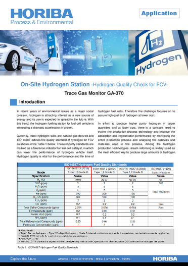
In recent years of environmental issues, as a major social concern, hydrogen is attracting interest as a new source of energy and its use is expected to spread in the future.
With this trend, the hydrogen fueling stations for fuel-cell vehicle is witnessing a dramatic acceleration in growth. Currently, most hydrogen fuels are natural gas derived and ISO-14687 defines the quality standard of hydrogen for FCEV. Hydrogen quality is vital for the performance and lifetime of hydrogen fuel cell, even trace level contamination is critical and may reduce the performance, lead to deterioration and damage of fuel cell catalyst.
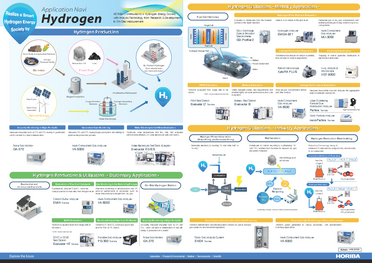
Therefore, the challenge focuses on to assure high quality of hydrogen at lower cost. In effort to produce higher purity hydrogen in larger quantities and at lower cost, there is a constant need to evolve the production process technology and to improve the adsorption and regeneration performance by monitoring the entire production process and analysing the catalysts and materials used in the process. Among the hydrogen production technologies, steam reforming is widely used as the most efficient way to produce large amounts of hydrogen.
This technology usually uses city gas and reforms it to the high purity hydrogen. In the process of reforming the row of impurities is produced together with the high purity hydrogen, therefore it is vitally important to continuously monitor critical impurities after pressure swing absorption unit to avoid its penetration to the final product - fuel-cell-grade hydrogen and to protect hydrogen fuel cell vehicles from performance deterioration.
Table 1: ISO14687 Hydrogen Fuel Quality Standards
On the Figure 1 below are shown 5 key steps in the basic operations of on-site hydrogen station.
Step 1: city gas (natural gas which mainly consists of methane) is directly supplied to hydrogen station trough pipeline.
Step 2: Sulfur compounds in natural gas are removed in desulfurization unit.
Step 3: Treated natural gas goes into steam methane reformer (SMR), which high temperature steam is used to convert methane into hydrogen and carbon monoxide (CH4+H2O=CO+3H2) .The high temperature accelerates reaction between methane and water to capture as much hydrogen as possible.
Step 4: Carbon monoxide and steam from reforming are going to CO shift converter to produce carbon dioxide and more hydrogen
(CO+H2O= H2+CO2).
This converter is filled with water and an iron-chrome based catalyst which causes steam to break down intro oxygen and hydrogen. Hydrogen is captured while oxygen attaches to carbon monoxide from the reforming reaction to produce carbon dioxide.
Step 5: Hydrogen is finally purified in the unit called pressure swing adsorption (PSA), which recovers high purity hydrogen at high pressure while absorbing impurities in low pressure. This unit uses beds of solid absorbent such as carbon molecular sieve to separate impurities from hydrogen stream.
Figure 1: Basic Operations of On-Site Hydrogen Station
CO is one of the worst unwanted impurity in hydrogen fuel cell because of difficulty of removal and catalyst poisoning, which can lead to voltage drop in fuel cell. Although in ISO-14687 hydrogen quality standards (See Table 2: ISO14687-3: 2019) there are many impurities needed to be monitored in very low concentration, monitoring of every impurity component is very challenging and cost consuming.
As a solution, there is impurity management method called “Canary Impurity Method” (See Table 3: Canary Impurity Management Method), which is specified in ISO standard. It is the method used as an index, which component is least removed in a hydrogen purification step and is easily mixed into a product. CO, which is an impurity in hydrogen, is determined as the canary component, and the quality of hydrogen is maintained by constantly monitoring the CO concentration as an index with continuous infrared analyzer. The reason why CO is least removed component is because it is indicated as break through component in PSA. When absorbent in pressure swing adsorption (PSA) reaches saturation due to its deterioration, CO comes out from it first.
HORIBA's Trace Gas Monitor (GA-370) is used to monitor breakthrough component which is CO to ensure fuel-cell-grade quality of hydrogen for reasonable cost. Carbon monoxide is to be checked in the outlet of pressure swing adsorption.
Table 2: ISO14687-3: 2019
Table 3: Canary Impurity Management Method
Reference:JXTG Technical Review Vol.60 No.01 (March 2018)
Development of a new quality control method for ENEOS Hydrogen
HORIBA's Trace Gas Monitor GA-370 (Shown in Figure 2) provides powerful analytical solutions to continuously monitor CO after pressure swing adsorption (PSA) in sub-part-per-billion (ppb) level.
It uses a principle called cross-modulation dual-beam non-dispersive infrared which results in zero-drift free measurement and reliable ultrasensitive detection of trace amounts of contaminant's molecules to ensure fuel-cell grade hydrogen quality.
With decades of experience in measurement solutions, HORIBA designed this analyzer to eliminate routine calibration cycles and to provide long term stable measurement and continuous unattended operations.
Every element in the analyzer has been selected to realise ultimate reliability, accuracy and ultra sensitivity for satisfaction most demanding industries and applications.
Cost effective, extremely stable and ultra sensitive – the best solution for wise hydrogen quality control and quality assurance management.
Table 4: Specification
GA-370 Introduction Video
Introduction of HORIBA's Trace Gas Monitor GA-370
Figure 2: Trace Gas Monitor GA-370
Cross Modulation Dual-Beam Non-Dispersive Infrared Analyzer
Molecules consisting of different atoms are known to absorb infrared light in a specific wavelength range.
Non-dispersive infrared analyzer (later, NDIR) uses above physical property of molecules and measures infrared light absorption in the specific wavelength of CO, CO2, and/or CH4 in the sample gas and provides continues measurement of concentration value.
Conventional NDIR technique used to have two measurement cells and rotating sector (optical chopper) to obtain modulation signal. HORIBA original NDIR with cross-modulation technology uses one measurement cell. The essential new element of design is a solenoid valve, which switches at a constant period (e.g.1Hz) and introduces the sample gas and the reference gas (zero gas) to the measurement cell alternately. By this method, the distinction between the sample and reference optical path is eliminated and the same optical path alternately functions as sample and reference optical path. The requirement of an optical chopper to modulate the detector output is thereby eliminated. The presence of CO, CO2 and/or CH4 in the sample gas generates a difference in the intensity of light reaching the detector when the cell is filled with sample gas as compared to when the cell is filled with reference gas. This difference causes the metallic membrane in the detector to move back and forth, which is corresponded to concentration value.
This measurement technique eliminates any need of an optical chopper or optical adjustments, enables zero drift free measurement, enhances sensitivity and provides long term stability.
Cross-modulation dual-beam NDIR is the same technique as cross-modulation described above, but instead of one measurement cell, sample gas and reference gases are alternately introduced into two measurement cells (See Figure 3). By acquiring signal from two cells, we have managed to have double amount of signal, what contributed to the high sensitivity of the measurement.
In addition, the signal-to-noise ratio is significantly better because the optical chopper which tends to create significant noise in a conventional NDIR is removed.
This technique has adopted dual detector system to minimize interference by other non-measured components coexisting in sample gas.
A compensating detector is located behind the main detector.The signal of measurement component + interference component is extracted by the main detector, and the signal of interference component is extracted by the compensating detector. These signals are amplified and calculated by subtractor to extract the output of only the target measurement component. Such dual detector design enables highly accurate measurement and ppb level precision.
Cross-Modulation Dual-Beam Non-Dispersive Infrared Technique. Flow Schematic
Graph 1 shows the noise level in cross-modulation dual-beam NDIR. It is obvious at a glance that the noise level equal to zero, the analyzer’s reading is extremely stable.
Summarizing, cross-modulation dual-beam NDIR, our HORIBA original technology guarantees long term stability, no optical noise and free of drift operations even when measuring trace level concentrations within high purity gas.
Graph 1: Cross-Modulation Dual-Beam NDIR Noise Level
Trace Gas Monitor
Do you have any questions or requests? Use this form to contact our specialists.