Raman and Resonance Raman Spectroscopy of Enzymes

The TRIAX and iHR series spectrometers used in Raman system configurations provide superior imaging performance with no re-diffracted light and maximized optical throughput.
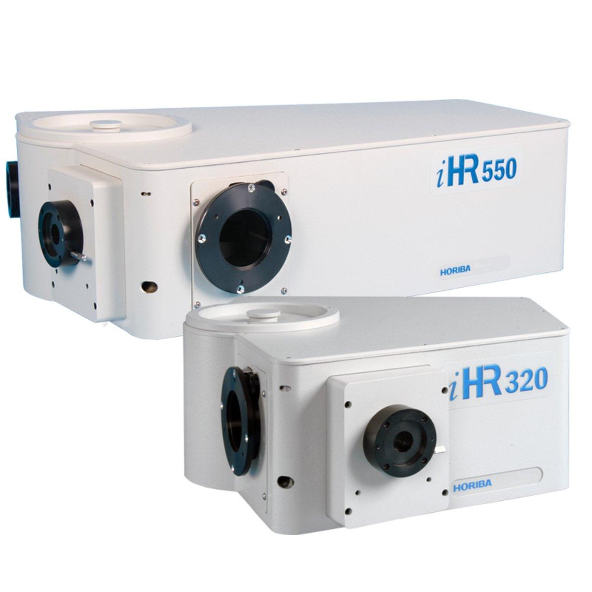
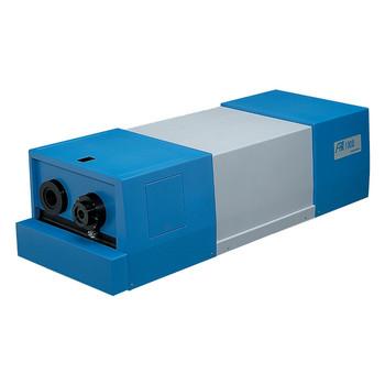
Mid-Focal Length Imaging Spectrometers
The iHR Series of 320 mm and 550 mm focal length high performance and versatile imaging spectrometers are HORIBA’s most popular and iconic spectrometers. The iHR series is built on decades of experience in spectroscopy and represents the highest quality, performance and versatility of any spectrometers in this class. The iHR 320 and iHR 550 spectrometers are immediately recognizable around the world by their unique shape, the result of a superior optical design. These spectrometers benefit from the highest quality of gratings, also designed and manufactured by HORIBA. The iHR series is ideal for applications such as:
If you are looking for OEM compact imaging spectrometers for prototyping or large quantities please visit our OEM division.
Find out what makes the iHR Series better imaging spectrometers!
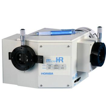
There is a wide selection of gratings to choose from depending on optical requirements. Gratings are 32 x 32 mm for the MicroHR. There are three different types of gratings available; classically ruled, holographic, and blazed holographic. There is also a flat mirror that may be ordered for the dual grating turret option. Please click on the link below to view all our grating options.
In addition to wavelength control the iHR Series has an optional automated turret control and automated control of the optional internal five position filter wheel. There are multiple software platforms to choose from for spectrometer control and acquisition. Please click on the link below to view all our software choices.
The iHR Series is compatible with many optical accessories to create your custom solution. Please click on the link below to view some of our optical accessories.
| iHR 320 | iHR 550 | ||
|---|---|---|---|
| Focal Length | 320 mm | 550 mm | |
| Aperture | f/4.1 | f/6.4 | |
| Spectral Range | 150 to 1500 nm w/ 1200 g/mm grating 150 nm to 40 µm w/ appropriate gratings | 150 to 1500 nm w/ 1200 g/mm grating 150 nm to 40 µm w/ appropriate gratings | |
| Grating Size | 68 mm x 68 mm | 76 mm x 76 mm | |
| Number of Gratings on Turre | up to 3 | up to 3 | |
| Flat Field Size | 30 mm x 12 mm | 30 mm x 12 mm | |
| Wavelength Accuracy | ± 0.20 nm | ± 0.20 nm | |
| Repeatability | ± 0.075 nm | ± 0.075 nm | |
| Spectral Dispersion (@500 nm) | 2.31 nm/mm | 1.34 nm/mm | |
| Magnification | 1.1 | 1.1 | |
| Stray Light* | 1.5 x 10⁻⁴ | 1 x 10⁻⁵ | |
| Scan Speed | 160 nm/sec | 160 nm/sec | |
| Step Size | 0.002 nm | 0.002 nm | |
| Computer Interface | Hi-Speed USB | Hi-Speed USB | |
| Dimensions | Length | 417 mm (16.4 in) | 648 mm (25.51 in) |
| Width | 422 mm (16.6 in) | 460 mm (18.09 in) | |
| Height | 192 mm (7.6 in) | 193 mm (7.78 in) | |
| Weight | 20 kg (45 lb) | 28 kg (62 lb) | |
*Stray measured at 1 nm from 514 nm laser with HORIBA Scientific Holographic Gratings.
Sie haben Fragen oder Wünsche? Nutzen Sie dieses Formular, um mit unseren Spezialisten in Kontakt zu treten.
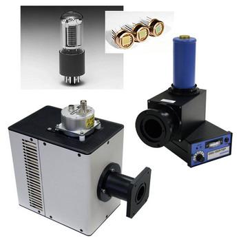
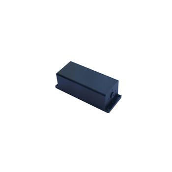
Dual Mode Analog/Photon Counting PMT
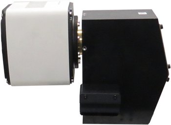
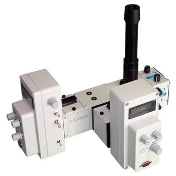
Confocal Raman & High-Resolution Spectrometer
Large choice of PMTs, solid state, photoelectric detectors for custom spectroscopy solutions
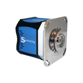
Deep Cooled NIR Scientific Cameras
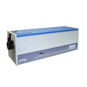
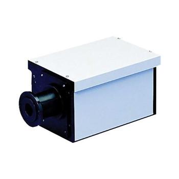
Long Focal Length Spectrometer
Dual Mode Analog/Photon Counting PMT
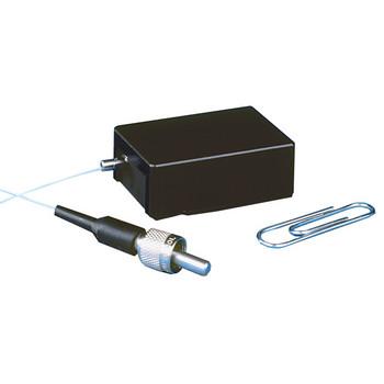
OEM miniature spectrograph
TCSPC Pulsed Sources
Random Access Monochromator
High Resolution Monochromators
Double monochromator
Compact Deuterium, Tungsten Halogen or Glow Bar Light Source
High Sensitivity Imaging Spectrograph
Short Focal Length Imaging Spectrometers
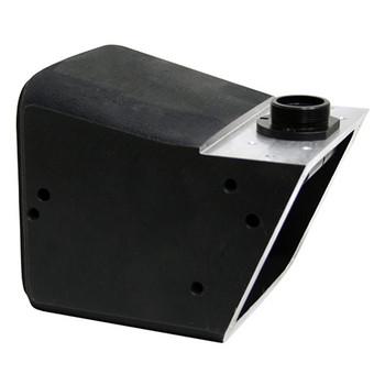
Ideal for Electrophysiology researchers to quantitate light intensity out of a microscope
Only available for volume OEM purchase, minimum order quantity 50 units.
Self contained PMT housing for quantitative spectroscopy and imaging low light measurements
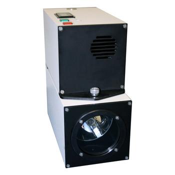
Broadband Xe Light Source
Deep Cooled UV/Vis/NIR
Large choice of PMTs, solid state, photoelectric detectors for custom spectroscopy solutions
Laser-induced Breakdown Spectroscopy (LIBS)
EMCCD Scientific Camera
Deep Cooled NIR Scientific Cameras
OEM CCD Camera
Deep Cooled Vacuum Ultra Violet Scientific Cameras
Tunable Broadband Light Sources
Tunable 75W Xe Light Source