Associate Professor Takashi Sasabe, from the Department of Mechanical Engineering, Tokyo Institute of Technology, Japan.
The following is based on an interview and all comments are quoted from the subject, Takashi Sasabe.
Fuel cell technology is one of the most promising clean energy areas that doesn’t emit greenhouse gases as a by-product. It is receiving more attention and has already started to be used in practical vehicles. However, there are still further challenges to improve the cost performance and the performance of fuel cell systems. HORIBA interviewed Associate Professor Takashi Sasabe at the Tokyo Institute of Technology, who is engaging in research to develop fuel cell systems with higher efficiencies.
Fuel cell devices generate electricity through chemical reactions of hydrogen and oxygen. The reaction does not emit greenhouse gas as by-products. Therefore, they are seen as key assets for clean energy. Fuel cell technology is already at the practical stage in the automotive industry, but for further commercialization, there are still further challenges in cost reductions and the performance improvement of durability and efficiencies.
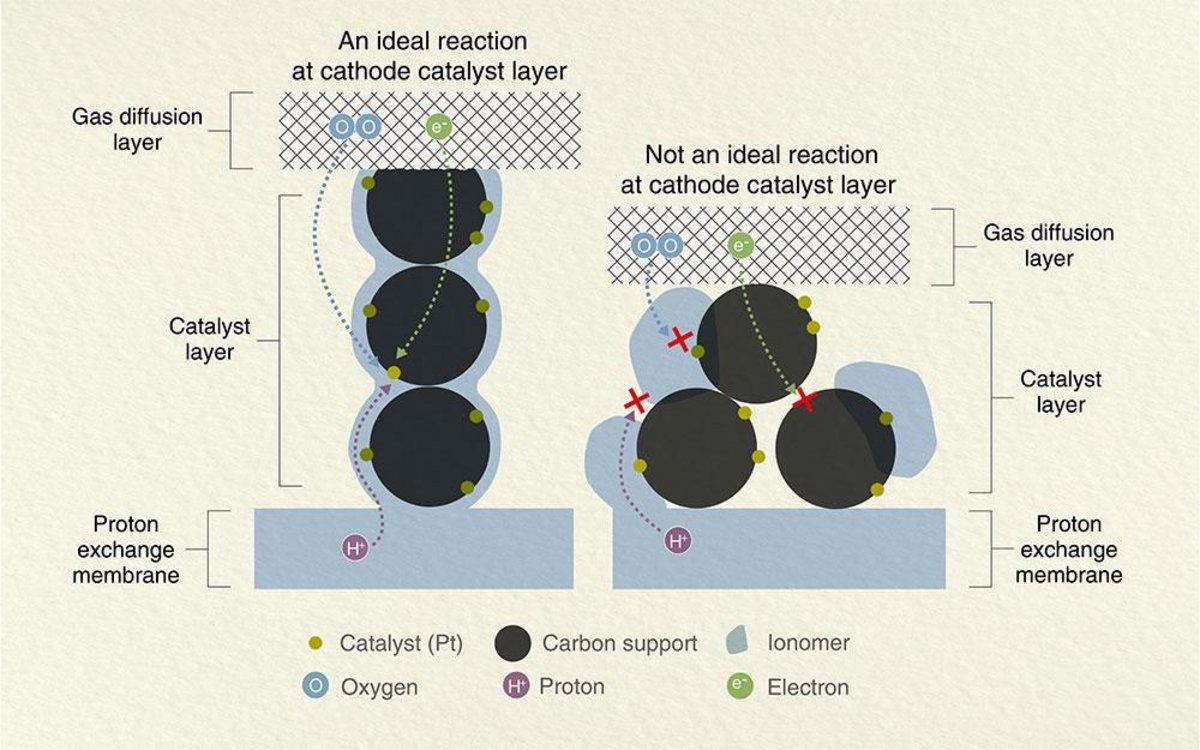
For an efficient fuel cell system, well-designed “reaction sites” are essential to boost the chemical reaction more smoothly. In a fuel cell system, hydrogen and oxygen are supplied from each end of the sandwich structure of a fuel cell, and the essential chemical reactions happen once they meet in the inner layers. For example, the important things in the cathode design are how to achieve smooth transportation of electrons(e+), proton (H+), and oxygen (O2) to the reaction sites and how to make the reactions happen more efficiently (Figure 1).
The catalyst layer of a fuel cell has a complex structure, which is a mixture of carbon supports, precious metal catalysts, ionomer, and organic solvents.[1] The mixture is called catalyst ink, and the ink consists of nanomaterials.For example, a platinum nanoparticle is one of the most popular catalyst materials and the diameter is normally a single nanometer. The metal catalyst particles are supported by carbon particles with larger diameters (approximately in 50 nano meters). Moreover, the ink is coated and dried-up to make into a thin sheet down to 10 µm. It means that all the necessary chemical reactions happen in such nano-/micro-structures of the catalyst layer. This is one of the reasons why the material design and the mechanism understanding are important but challenging to achieve.
Figure 1. Schematic diagram of the ideal reaction at the cathode catalyst layer in a fuel cell.
The smooth transportation of electron (e-), proton (H+), and oxygen(O2), and more active reaction sites for these are important in a cathode catalyst layer design. An ionomer is an important factor in proton (H+) transportation, so the ionomer should be well-coated around carbon-supported catalysts. At the same time, the ionomer is inefficient for oxygen (O2) transportation, so the coating should be well-controlled not to be too thick. To achieve the best transportation both for proton (H+) and oxygen (O2), ionomer dispersion in a catalyst ink is key, and particle size distribution analysis is an important method to visualize the dispersion or aggregation in the ink.
The catalyst ink used for a fuel cell is normally in a high-concentration state. On the other hand, sample dilution is a mandatory pre-treatment for particle size distribution analysis of a black color material like the catalyst ink. The issue is that the particle size distribution result might change from the working components, once the sample is diluted. We consulted with many suppliers of particle size analyzers to learn if there is any breakthrough to produce particle size distribution results without sample dilution. Almost all their replies were “No, sorry” or “Please accept dilution.” Only HORIBA gave us a positive reply. “Yes, we have a solution for it.” HORIBA tested our samples and we validated the results by comparing it with our conventional method using transmitted electron microscopy.
We were really surprised that we could get an expected particle size distribution result without dilution for our samples. It was a really exciting achievement which no one had ever reached.
We also found that the particle size distribution result was different if we performed dilution for the analysis. If we didn’t know HORIBA’s solution, we might have believed the wrong results without noticing it.
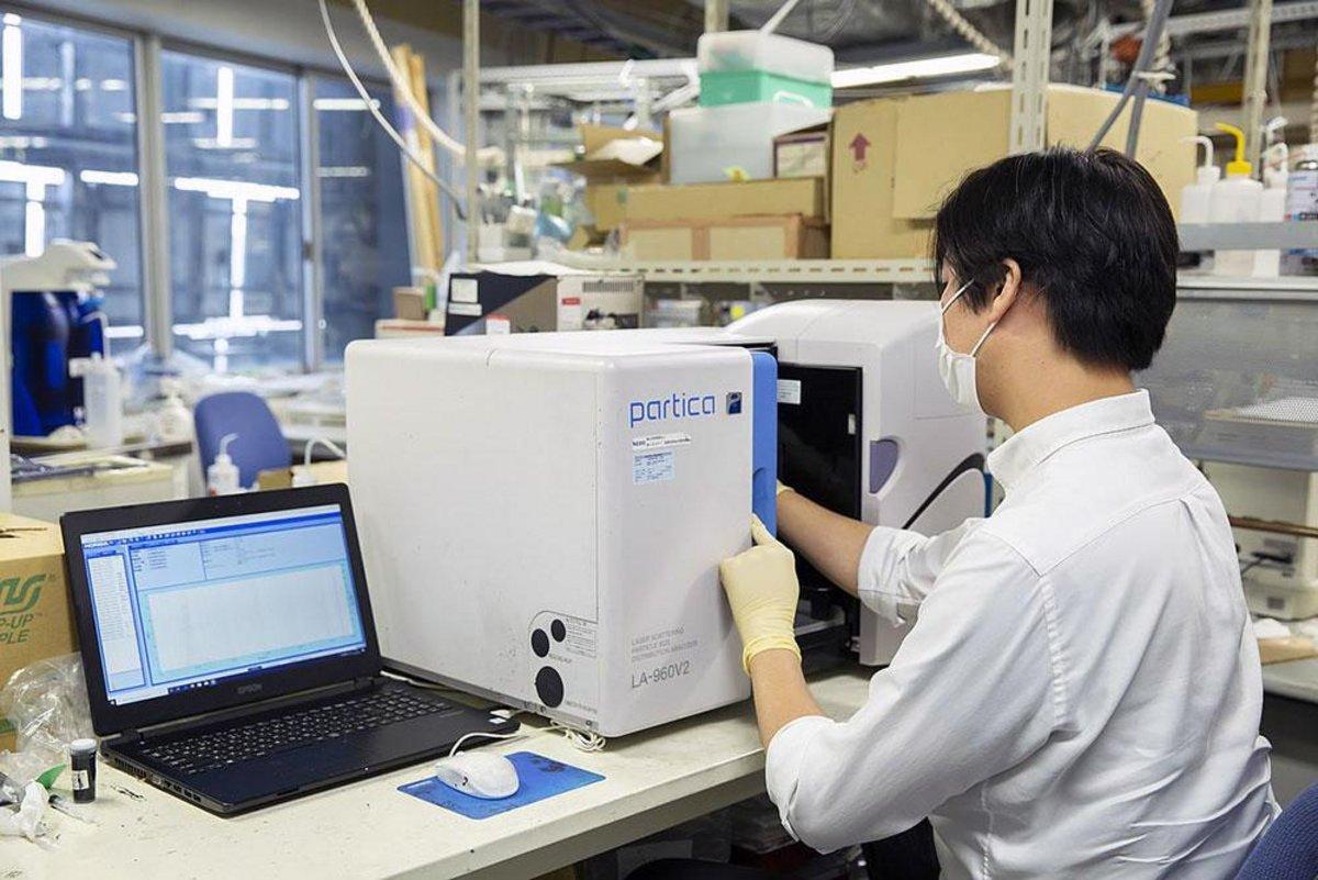
The instrument used was the Partica LA-960V2 Laser Scattering Particle Size Distribution Analyzer.
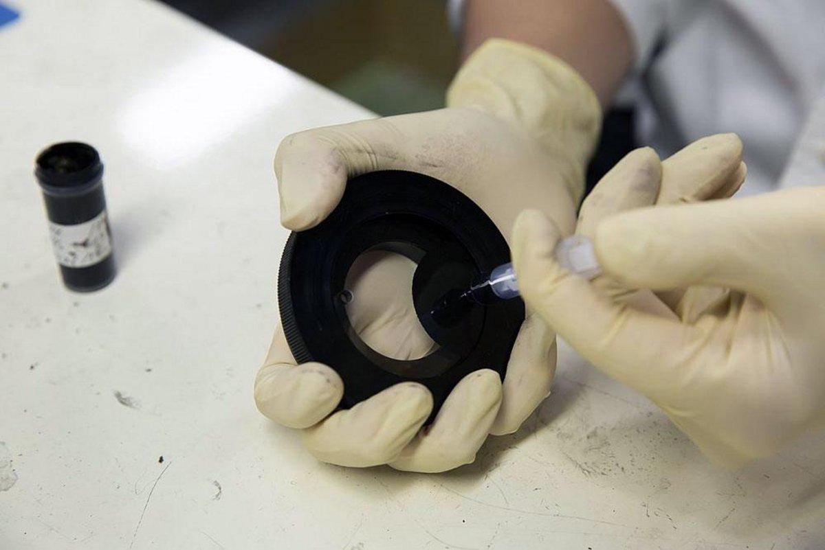
The high concentration cell attachment of the HORIBA LA-960 series. This photo shows adding the catalyst ink into the cell.
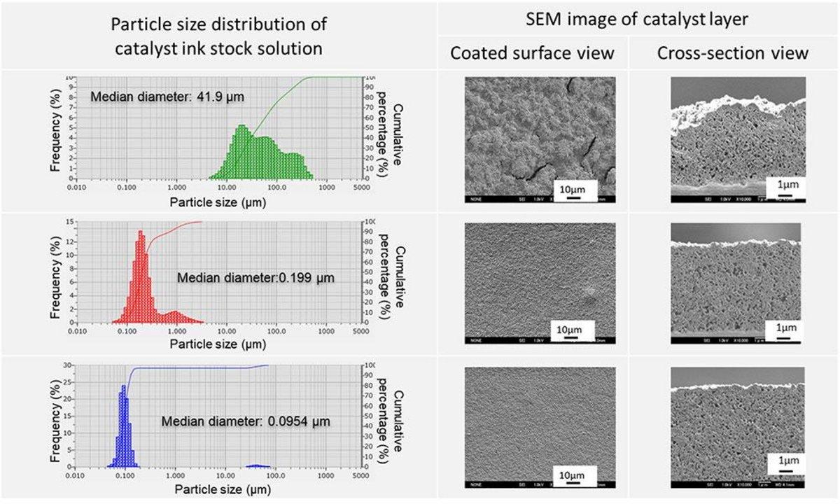
We are aiming to predict the structure of the catalyst layer by knowing how the catalyst ink was dispersed.
It was very difficult to comprehend the dispersion structure of catalyst ink. Although we can observe the nanoscale structure of catalyst ink by electron microscope, the only localized image can be obtained. In addition, the polymer materials like catalyst ink may be damaged by electron beam.
Thus, it is necessary to assemble an actual fuel cell by using various materials with the conventional method to evaluate a correlation between materials used for catalyst layer and performance of fuel cells, spending a lot of time and cost.
However, our research enables us to predict the structure of the catalyst layer from the dispersion state of the catalyst ink prepared by various materials. So, we expect that the number of experimental steps for evaluation of power generation performance of fuel cells could be dramatically reduced.
Performing consistency checks between the LA-960 results and the SEM observation results.
Associate Professor Takashi Sasabe
Catalyst ink is reported as a non-Newtonian fluid and the aggregate state of the catalyst ink changes when a strong shear force is applied. When we use the slot-die coating method, which is a method pushing the catalyst ink out through a thin slit to coat, it causes a strong shear force to the catalyst ink and it makes the aggregate state change. Therefore, it is important to observe the aggregation exactly under shear force ink. In addition, the catalyst ink aggregate stage also changes once it gets dried. Therefore, the drying process after extrusion is also an important step for the mass production of high-quality catalyst layers.
Model-based development is getting more popular in the scientific field. There is a strong demand from the automotive industry to demonstrate the mechanism and power generation performance of the catalyst layer by model-based simulation of the material properties. However, the catalyst layer formation mechanism from catalyst ink is still not yet clear. Therefore, there are fewer simulated results about the mechanism. Moreover, experimental results on catalyst inks are also limited. Therefore, we couldn’t confirm whether the simulation results were reasonable or not. I believe our research using particle size distribution analysis under more realistic conditions makes it possible for us to discuss the aggregate state of catalyst ink. It enables us to get the correlation between the particle size distribution of catalyst ink and catalyst layer structure through experiments, and it will eventually help us develop more reliable simulations.
Thanks to the HORIBA’s solution, we could be the first research team who report the aggregate state of the catalyst ink without dilution. The report was the first reported during an international conference of fuel cell research, and we received many inquiries from other researchers about the application for their catalyst inks.
When we looked back, if we had not discovered the HORIBA’s solution, we would have still kept looking for other methods to understand the catalyst ink state and we wouldn’t have achieved a positive outcome. Our achievement using the HORIBA particle size analyzer with its high-concentration cell made it possible for us to understand the catalyst ink state, and it also brought many changes to our research.
We would like to further develop our research so that we can predict the dispersion state of catalyst ink based on the physical properties of the materials. It has become clear that the dispersion state of catalyst ink has a significant effect on the catalyst layer structure, but it is still difficult to predict the dispersion state of catalyst ink from the physical properties of the materials. We hope we can predict something like 'Once we change the wettability of a carbon material, the interaction with polymers and solvents may change like this. If a material has this kind of wettability, the catalyst ink will be more dispersed and the catalyst layer structure will be like this, resulting in a fuel cell with higher performance.’ in near future.
HORIBA LA-960V2
https://www.horiba.com/int/scientific/products/detail/action/show/Product/partica-la-960v2-1944/
Learn more about HORIBA Fuel Cell Evaluation Technology
https://www.horiba.com/int/applications/energy-and-environment/hydrogen/fuel-cell-evaluation/
[1] FC-Cubic, Technical Information, "MEA Preparation" https://www.fc-cubic.or.jp/en/pages/technical-info/ (Viewed om 17th Feb. 2024)
如您有任何疑问,请在此留下详细需求信息,我们将竭诚为您服务。


